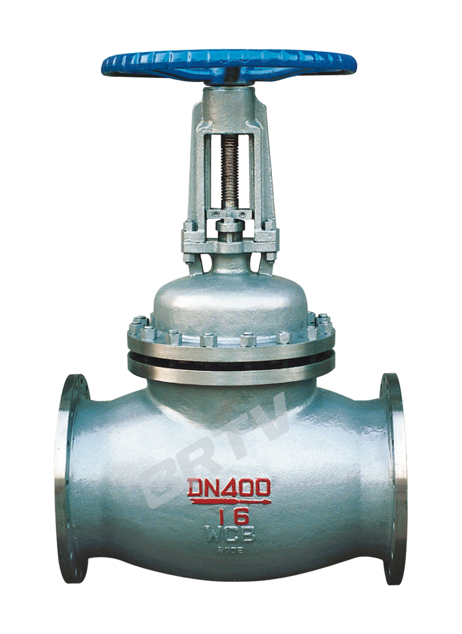
Product Overview
Piston valve is a new product developed on the basis of extensive research and summary of stop valve and plunger valve. This new piston valve has many advantages: first, it adopts doubleSeal, (first metal to metal axial seal, then flexible seal ring to stainless steel valve seat radial seal) so the sealing performance is particularly good. Second, it has a long service life due to its pistonThe ring (flexible seal ring) is installed on the piston, so it is not directly eroded by the medium. Third, the flow of medium through the piston valve is large and the flow resistance is small. Fourth, the opening and closing stroke is short, occupying spaceSmall, more conducive to indoor or narrow space. Fifth, the maintenance is very convenient. If the valve leaks after long-term use, just turn the hand wheel a little more when it is closed, It can produce axial force, and the flexible seal ring will expand radially under the action of axial pressure, so the original sealing performance can be restored. If it is convenient to replace the sealing ring, take out the piston and replace it Piston ring.
It is widely used in the pipe network of water, gas and hot oil, steam and viscous medium ≤ 250 ℃. (if you need to use temperature ≤ 390 ℃ or ≤ 550 ℃, you can customize high-temperature sealing ring).
Technical Specifications
| Type | Nominal Pressure (PN) | Shell Test (MPa) | Liquid Seal Test (MPa) | Gas Seal Test (MPa) | Applicable Medium | Applicable Temperature (°C) | High Temperature (°C) |
|---|
| HSF11S-16CP | 1.6 | 2.40 | 1.76 | 0.6 | Steam / Gas / Oil Gas / Nitric Acid / Acetic Acid | ≤200 | — |
| HSF41S-16 | 1.6 | 2.40 | 1.76 | 0.6 | Steam / Gas / Oil Gas | ≤200 | ≤450 |
| HSF41S-16C | 1.6 | 2.40 | 1.76 | 0.6 | Steam / Gas / Oil Gas | ≤250 | ≤450 |
| HSF41S-25C | 2.5 | 3.75 | 2.80 | 0.6 | Steam / Gas / Oil Gas | ≤250 | ≤450 |
| HSF41S-40C | 4.0 | 6.00 | 4.40 | 0.6 | Steam / Gas / Oil Gas | ≤250 | ≤450 |
| HSF41S-64C | 6.4 | 9.60 | 7.04 | 0.6 | Steam / Gas / Oil Gas | ≤250 | ≤450 |
| HSF41S-100C | 10 | 15.00 | 11.00 | 0.6 | Steam / Gas / Oil Gas | ≤250 | ≤450 |
| HSF41F-16PR | 1.6 | 2.40 | 1.76 | 0.6 | Nitric Acid / Acetic Acid | ≤200 | — |
| HSF41F-25PR | 2.5 | 3.75 | 2.80 | 0.6 | Nitric Acid / Acetic Acid | ≤200 | — |
| HSF41F-40PR | 4.0 | 6.00 | 4.40 | 0.6 | Nitric Acid / Acetic Acid | ≤200 | — |
| HSF41S-10(Z) | 1.0 | 1.50 | 1.10 | 0.6 | Steam / Gas / Oil Gas | ≤250 | — |
| HSF41S-16(Z) | 1.6 | 2.40 | 1.76 | 0.6 | Steam / Gas / Oil Gas | ≤250 | — |
| HSF41S-25(Z) | 2.5 | 3.75 | 2.80 | 0.6 | Steam / Gas / Oil Gas | ≤250 | — |
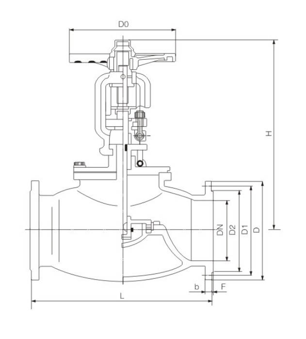
Main Dimension
HSF41S-1.6 Main Dimensions
| DN (mm) | L | D | D1 | D2 | D0 | Z-Φd | b | H |
|---|
| 25 | 160 | 115 | 85 | 65 | 120 | 4-14 | 16 | 214 |
| 32 | 180 | 135 | 100 | 78 | 140 | 4-18 | 18 | 220 |
| 40 | 200 | 145 | 110 | 85 | 160 | 4-18 | 18 | 243 |
| 50 | 230 | 160 | 125 | 100 | 180 | 4-18 | 20 | 283 |
| 65 | 290 | 180 | 145 | 120 | 200 | 4-18 | 20 | 304 |
| 80 | 310 | 195 | 160 | 135 | 240 | 8-18 | 20 | 331 |
| 100 | 350 | 215 | 180 | 155 | 280 | 8-18 | 24 | 370 |
| 125 | 400 | 245 | 210 | 185 | 350 | 8-18 | 26 | 510 |
| 150 | 480 | 280 | 240 | 210 | 400 | 8-23 | 28 | 549 |
| 200 | 600 | 335 | 295 | 265 | 460 | 12-23 | 30 | 560 |
HSF41S-1.6C / P / R Main Dimensions
| DN (mm) | L | D | D1 | D2 | D0 | Z-Φd | b | H |
|---|
| 25 | 160 | 115 | 85 | 65 | 120 | 4-14 | 16 | 214 |
| 32 | 180 | 135 | 100 | 78 | 140 | 4-18 | 18 | 220 |
| 40 | 200 | 145 | 110 | 85 | 160 | 4-18 | 18 | 243 |
| 50 | 230 | 160 | 125 | 100 | 180 | 4-18 | 20 | 283 |
| 65 | 290 | 180 | 145 | 120 | 200 | 4-18 | 20 | 304 |
| 80 | 310 | 195 | 160 | 135 | 240 | 8-18 | 20 | 331 |
| 100 | 350 | 215 | 180 | 155 | 280 | 8-18 | 24 | 370 |
| 125 | 400 | 245 | 210 | 185 | 350 | 8-18 | 26 | 510 |
| 150 | 480 | 280 | 240 | 210 | 400 | 8-23 | 28 | 549 |
| 200 | 600 | 335 | 295 | 265 | 460 | 12-23 | 30 | 560 |
| 250 | 730 | 405 | 355 | 320 | 550 | 12-25 | 32 | — |
| 300 | 750 | 460 | 410 | 375 | 550 | 12-25 | 32 | — |
| 350 | 787 | 520 | 470 | 435 | 600 | 16-25 | 34 | — |
| 400 | 914 | 580 | 525 | 485 | 800 | 16-30 | 36 | — |
| 450 | 978 | 640 | 585 | 545 | 800 | 20-30 | 40 | — |
| 500 | 978 | 705 | 650 | 608 | 850 | 20-34 | 44 | — |
HSF41S-2.5 C.P.R
| DN (mm) | L | D | D1 | D2 | D0 | Z-Φd | b | H |
|---|
| 25 | 160 | 115 | 85 | 65 | 120 | 4-14 | 16 | 214 |
| 32 | 180 | 135 | 100 | 78 | 140 | 4-18 | 18 | 220 |
| 40 | 200 | 145 | 110 | 85 | 160 | 4-18 | 18 | 243 |
| 50 | 230 | 160 | 125 | 100 | 180 | 4-18 | 20 | 283 |
| 65 | 290 | 180 | 145 | 120 | 200 | 8-18 | 22 | 304 |
| 80 | 310 | 195 | 160 | 135 | 240 | 8-18 | 22 | 331 |
| 100 | 350 | 230 | 190 | 160 | 280 | 8-23 | 24 | 370 |
| 125 | 400 | 270 | 220 | 188 | 350 | 8-25 | 28 | 510 |
| 150 | 480 | 300 | 250 | 218 | 400 | 8-25 | 30 | 549 |
| 200 | 600 | 360 | 310 | 278 | 460 | 12-25 | 34 | 498 |
| 250 | 730 | 425 | 370 | 332 | 550 | 12-30 | 36 | 570 |
| 300 | 750 | 485 | 430 | 390 | 550 | 16-30 | 40 | — |
| 350 | 787 | 550 | 490 | 450 | 600 | 16-34 | 44 | — |
| 400 | 914 | 610 | 550 | 505 | 800 | 16-34 | 48 | — |
| 450 | 978 | 660 | 600 | 555 | 800 | 20-34 | 50 | — |
| 500 | 978 | 730 | 660 | 610 | 850 | 20-41 | 52 | — |
HSF41S-4.0 C.P.R
| DN (mm) | L | D | D1 | D2 | D0 | Z-Φd | b | H |
|---|
| 25 | 160 | 115 | 85 | 65 | 120 | 4-14 | 16 | 214 |
| 32 | 180 | 135 | 100 | 78 | 140 | 4-18 | 18 | 220 |
| 40 | 200 | 145 | 110 | 85 | 160 | 4-18 | 18 | 243 |
| 50 | 230 | 160 | 125 | 100 | 180 | 4-18 | 20 | 283 |
| 65 | 290 | 180 | 145 | 120 | 185 | 8-18 | 22 | 304 |
| 80 | 310 | 195 | 160 | 135 | 200 | 8-18 | 22 | 331 |
| 100 | 350 | 230 | 190 | 160 | 240 | 8-23 | 24 | 370 |
| 125 | 400 | 270 | 220 | 188 | 250 | 8-25 | 28 | 510 |
| 150 | 480 | 300 | 250 | 218 | 250 | 8-25 | 30 | 549 |
| 200 | 600 | 375 | 320 | 282 | 460 | 12-30 | 38 | — |
| 250 | 730 | 445 | 385 | 345 | 460 | 12-34 | 42 | — |
| 300 | 750 | 510 | 450 | 410 | 550 | 16-34 | 46 | — |
| 350 | 778 | 570 | 510 | 465 | 600 | 16-34 | 52 | — |
HSF41S-6.4 C.P.R
| DN (mm) | L | D | D1 | D2 | D6 | b | Z-Φd | D0 |
|---|
| 25 | 210 | 135 | 100 | 78 | 58 | 22 | 4-18 | 180 |
| 32 | 230 | 150 | 110 | 82 | 66 | 24 | 4-23 | 200 |
| 40 | 260 | 165 | 125 | 95 | 76 | 24 | 4-23 | 240 |
| 50 | 300 | 175 | 135 | 105 | 88 | 26 | 4-23 | 280 |
| 65 | 340 | 200 | 160 | 130 | 110 | 28 | 8-23 | 320 |
| 80 | 380 | 210 | 170 | 140 | 121 | 30 | 8-23 | 360 |
| 100 | 430 | 250 | 200 | 168 | 150 | 32 | 8-25 | 400 |
| 125 | 500 | 295 | 240 | 202 | 176 | 36 | 8-30 | 450 |
| 150 | 550 | 340 | 280 | 240 | 204 | 38 | 8-34 | 500 |
| 200 | 650 | 405 | 345 | 300 | 260 | 44 | 12-34 | 560 |
| 250 | 775 | 470 | 400 | 352 | 313 | 48 | 12-41 | 640 |
| 300 | 900 | 530 | 460 | 412 | 364 | 54 | 16-41 | 800 |
Manufacturing Process
Step 1: Order and Design
Based on the pressure rating, nominal diameter, connection type, and operating conditions provided by the customer, we determine the structural configuration, material requirements, and manufacturing standards for the piston valve. We then complete the drawing design, process review, and production planning.
Step 2: Forging & Casting
In accordance with the component requirements for the piston valve, we cast or forge the main pressure-bearing components, such as the valve body and valve bonnet. After the blanks are formed, perform sand removal, deburring, and preliminary visual inspection to ensure there are no defects such as cracks or porosity.
Step 3: Machining
Perform precision machining on the valve body, bonnet, stem, piston, and sealing mating surfaces. Key machining operations for the piston valve include internal bore dimensional control, sealing surface machining, threading, and flange face finishing to ensure assembly accuracy and sealing performance.
Step 4: Assembly
After cleaning the machined parts, they are assembled in sequence according to the assembly process. The main assembly steps for piston valves include installing components such as the piston, valve stem, seal rings, gland, and handwheel, followed by checking for smooth and flexible operation.
Step 5: Testing & Quality Assurance
After assembly, the piston valve undergoes strength testing, seal testing, and operational testing. Simultaneously, dimensional re-inspection, visual inspection, and material traceability are conducted to ensure the product meets relevant quality standards and customer requirements.
Step 6: Painting and Finishing
After passing inspection, the valve surface undergoes sandblasting, primer application, and topcoat application to enhance corrosion resistance. Finally, labeling, nameplate attachment, packaging, and pre-shipment preparation are completed to ensure the piston valve meets transportation and delivery requirements.
Applications
- Water Inlet System: Used as relief valves or blow-off valves to control pipeline pressure
- Storage System: Used for level and pressure control valves
- Water Distribution System: Performs core functions such as flow control valves, drain valves, or pipe filling valves
- Water Treatment System: Used for pump start-up protection valves or air volume control valves
These valves are widely used in:
Agriculture and Irrigation
Factory Environment
Why Choose Us
Superior Quality

Our valves are manufactured using premium materials and undergo rigorous quality testing to ensure reliable performance in demanding industrial applications.
Advanced Technology

Equipped with state-of-the-art CNC machining centers and precision manufacturing equipment, we deliver valves with exceptional accuracy and consistency.
Competitive Pricing

Through optimized manufacturing processes and bulk material procurement, we offer high-quality valves at competitive prices without compromising on quality.
Expert Support

Our experienced technical team provides comprehensive support from product selection to after-sales service, ensuring optimal valve performance for your specific application.