Product Overview
It is mainly used as the connecting and cutting off device on the pipeline in industries of petroleum, chemical, metallurgy and pharmacy system and so on transporting the high viscosity medium which would be solidified under normal temperature.
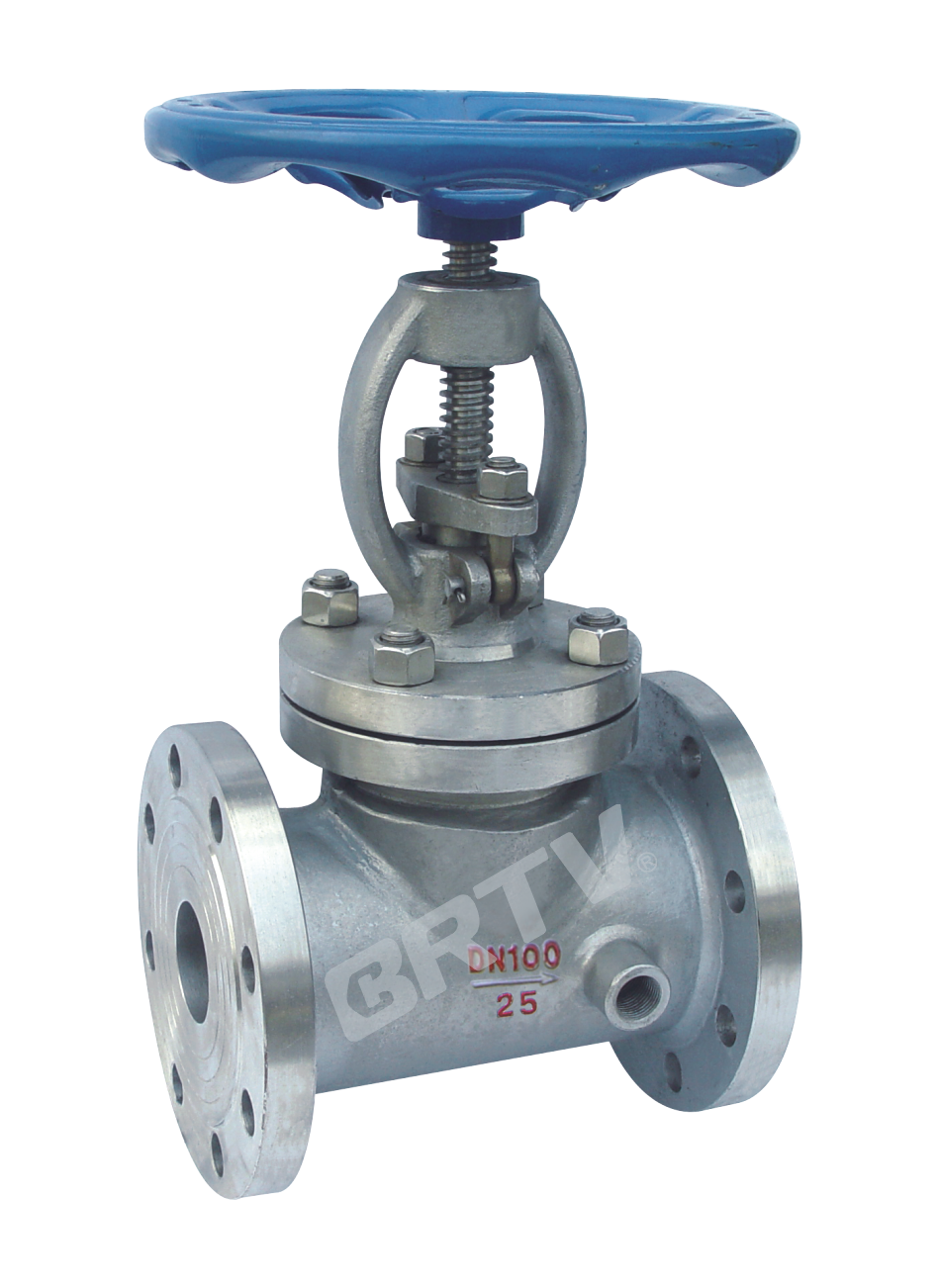
Product Features
- Outside screw and yoke;
- BB, bolted bonnet;
- Loose disc;
- Rising stem and handwheel;
- Yoke integral with bonnet.
Technical Specifications
| Design Basis | GB |
|---|
| Design Standard | GB/T 12235 / GB/T 12224 |
| Face-to-Face | GB/T 12221 |
| Flanged | GB/T 9113 |
| Test and Check | JB/T 9092 / GB/T 12224 |
Main parts and Materials
| Part Name | Carbon Steel (GB) | Carbon Steel (ASTM) | Stainless Steel (GB) | Stainless Steel (ASTM) |
|---|
| Body | WCB | A216-WCB | CF8 / CF8M | A351-CF8 / A351-CF8M |
| Bonnet | WCB | A216-WCB | CF8 / CF8M | A351-CF8 / A351-CF8M |
| Disc | 25 | A105 | 12Cr18Ni9 / 06Cr17Ni12Mo2 | A182-F304 / A182-F316 |
| Stem | 20Cr13 | A182-F6a | 12Cr18Ni9 / 06Cr17Ni12Mo2 | A182-F304 / A182-F316 |
| Bonnet Gasket | F.G / 12Cr18Ni9 | F.G / 304 | F.G / 12Cr18Ni9 | F.G / 304 |
| Bonnet Stud | 35CrMo | A193-B7 | 12Cr18Ni9 | A193-B8 |
| Bonnet Stud Nut | 45 | A194-2H | 12Cr18Ni9 | A194-8 |
| Packing | Flexible Graphite | Flexible Graphite | Flexible Graphite | Flexible Graphite |
| Packing Gland | WCB | A216-WCB | CF8 / CF8M | A351-CF8 / A351-CF8M |
| Eye Bolt | 45 | A307-B | 12Cr18Ni9 | A193-B8 |
| Yoke Sleeve | ZCuAl10Fe3 | C95500 | ZCuAl10Fe3 | C95500 |
| Hand Wheel | KTH350-10 | A47 / 32510 | KTH350-10 | A47 / 32510 |
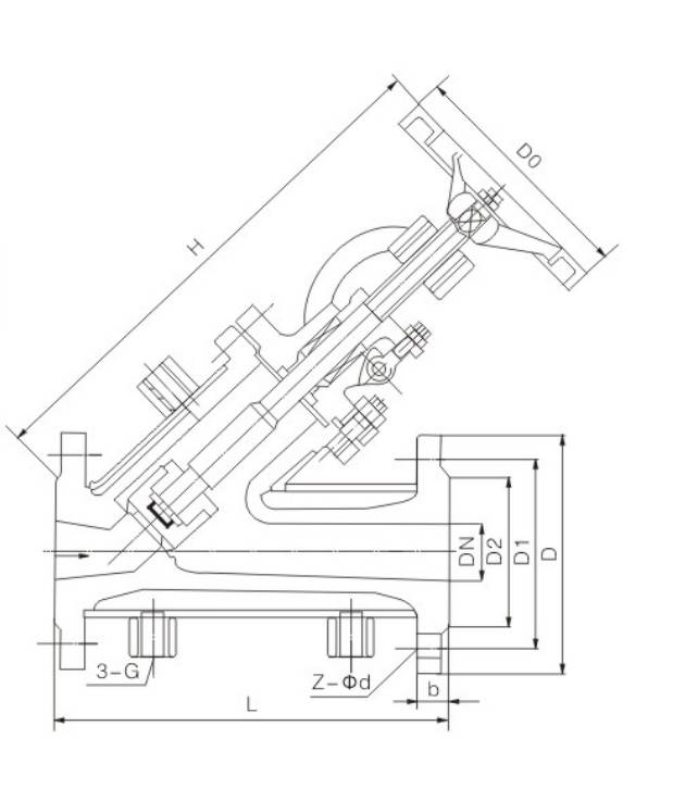
Main Dimension
BJ45 / 41H-16 Series
| Type | DN | Inner DN | Flange DN | L | H | D0 | WT (kg) |
|---|
| BJ45/41H-16 / BJ45/41Y-16P / BJ45/41Y-16R / BJ45/41Y-16R3 | 15 | 15 | 20 | 130 | 232 | 100 | 6 |
| 20 | 20 | 25 | 150 | 290 | 120 | 8 |
| 25 | 25 | 32 | 160 | 306 | 140 | 10 |
| 32 | 32 | 40 | 180 | 321 | 160 | 14 |
| 40 | 40 | 50 | 200 | 366 | 180 | 18 |
| 50 | 50 | 65 | 230 | 375 | 220 | 26 |
| 65 | 65 | 80 | 290 | 390 | 280 | 32 |
| 80 | 80 | 100 | 310 | 430 | 300 | 41 |
| 100 | 100 | 125 | 350 | 500 | 320 | 56 |
| 150 | 150 | 200 | 480 | 610 | 420 | 115 |
BJ45 / 41H-25 Series (PN 2.5 MPa)
| Type | DN | L | D | D1 | D2 | D6 | b | Z-Φd | G | H | D0 | WT (kg) |
|---|
| BJ45/41H-25 / BJ45/41Y-25P / BJ45/41Y-25R / BJ45/41Y-25R3 | 15 | 200 | 105 | 75 | 55 | — | 16 | 4-Φ14 | 1/2" | 210 | 120 | 15 |
| 20 | 220 | 115 | 85 | 65 | — | 16 | 4-Φ14 | 1/2" | 240 | 140 | 21 |
| 25 | 220 | 135 | 100 | 78 | — | 18 | 4-Φ18 | 1/2" | 250 | 160 | 25 |
| 32 | 250 | 145 | 110 | 85 | — | 18 | 4-Φ18 | 1/2" | 270 | 160 | 30 |
| 40 | 270 | 160 | 125 | 100 | — | 20 | 4-Φ18 | 1/2" | 310 | 160 | 36 |
| 50 | 300 | 180 | 145 | 120 | — | 22 | 8-Φ18 | 3/4" | 330 | 240 | 40 |
| 65 | 350 | 195 | 160 | 135 | — | 22 | 8-Φ18 | 3/4" | 360 | 240 | 54 |
| 80 | 380 | 230 | 190 | 160 | — | 24 | 8-Φ23 | 3/4" | 400 | 280 | 70 |
| 100 | 430 | 270 | 220 | 188 | — | 28 | 8-Φ25 | 1" | 480 | 320 | 100 |
| 125 | 490 | 300 | 250 | 218 | — | 30 | 8-Φ25 | 1" | 550 | 360 | 130 |
| 150 | 570 | 330 | 280 | 248 | — | 32 | 12-Φ25 | 1" | 620 | 300 | 170 |
| 200 | 690 | 395 | 340 | 302 | — | 36 | 12-Φ30 | 1" | 750 | 400 | 250 |
BJ45 / 41H-40 Series
| Type | DN | L | D | D1 | D2 | D6 | b | Z-Φd | G | H | D0 | WT (kg) |
|---|
| BJ45/41H-40 / BJ45/41Y-40P / BJ45/41Y-40R / BJ45/41Y-40R3 | 15 | 200 | 105 | 75 | 55 | 51 | 16 | 4-Φ14 | 1/2" | 210 | 120 | 18 |
| 20 | 220 | 115 | 85 | 65 | 58 | 16 | 4-Φ14 | 1/2" | 240 | 140 | 21 |
| 25 | 220 | 135 | 100 | 78 | 66 | 18 | 4-Φ18 | 1/2" | 250 | 160 | 25 |
| 32 | 250 | 145 | 110 | 85 | 76 | 18 | 4-Φ18 | 1/2" | 270 | 160 | 33 |
| 40 | 270 | 160 | 125 | 100 | 88 | 20 | 4-Φ18 | 1/2" | 310 | 160 | 41 |
| 50 | 300 | 180 | 145 | 120 | 110 | 22 | 8-Φ18 | 3/4" | 330 | 240 | 45 |
| 65 | 350 | 195 | 160 | 135 | 121 | 22 | 8-Φ18 | 3/4" | 360 | 240 | 62 |
| 80 | 380 | 230 | 190 | 160 | 150 | 24 | 8-Φ23 | 3/4" | 400 | 280 | 80 |
| 100 | 430 | 270 | 220 | 188 | 176 | 28 | 8-Φ25 | 1" | 480 | 320 | 100 |
| 125 | 190 | 300 | 250 | 218 | 204 | 30 | 8-Φ25 | 1" | 550 | 360 | 130 |
| 150 | 570 | 350 | 295 | 258 | 234 | 34 | 12-Φ30 | 1" | 620 | 360 | 185 |
| 200 | 690 | 415 | 355 | 315 | 287 | 40 | 12-Φ34 | 1" | 750 | 400 | 168 |
Manufacturing Process
Step 1: Order and Design
Based on the operating conditions provided by the customer—such as nominal diameter, pressure rating, temperature, medium type, and jacket heating/insulation requirements—determine the structural configuration, main dimensions, seat sealing method, and jacket connection scheme for the jacketed globe valve, and complete the drawing design and process review.
Step 2: Forging & Casting
In accordance with the material requirements for the jacketed globe valve, key components such as the valve body, bonnet, and disc are forged or cast. The valve body must meet the structural strength requirements for both the main flow path and the jacket cavity. After casting, the components undergo desanding, heat treatment, and raw material inspection.
Step 3: Machining
Precision machining is performed on the valve body, bonnet, stem, disc, and flange sealing surfaces. The machining focus for the jacketed globe valve lies in the dimensional accuracy and concentricity of the main flow path, seat sealing surfaces, and jacket flow channel interfaces to ensure proper subsequent assembly and media circulation.
Step 4: Assembly
Assemble the machined parts in accordance with process requirements, including the valve seat, disc, stem, packing, bonnet, and handwheel. During the assembly of the jacketed globe valve, the fit of the jacket connection ports, gaskets, and connecting bolts must also be inspected to ensure a reliable seal between the valve body and the jacket section.
Step 5: Testing & Quality Assurance
After assembly, the jacketed globe valve undergoes shell strength testing, seal testing, operational testing, and jacket cavity leakage testing. Concurrently, the appearance, dimensions, material reports, and pressure test records are verified to ensure the product complies with relevant standards and customer requirements.
Step 6: Painting and Finishing
After passing inspection, the valve’s exterior surfaces are cleaned, treated with rust prevention, and spray-painted. Non-machined surfaces are painted as required, flange surfaces are properly protected, and nameplates, markings, packaging, and final pre-shipment inspections are completed.
Applications
It is primarily used in high-temperature, high-pressure environments or applications requiring medium insulation in industries such as chemicals, petroleum, and metallurgy.
These valves are widely used in:
Agriculture and Irrigation
Factory Environment
Why Choose Us
Superior Quality

Our valves are manufactured using premium materials and undergo rigorous quality testing to ensure reliable performance in demanding industrial applications.
Advanced Technology

Equipped with state-of-the-art CNC machining centers and precision manufacturing equipment, we deliver valves with exceptional accuracy and consistency.
Competitive Pricing

Through optimized manufacturing processes and bulk material procurement, we offer high-quality valves at competitive prices without compromising on quality.
Expert Support

Our experienced technical team provides comprehensive support from product selection to after-sales service, ensuring optimal valve performance for your specific application.