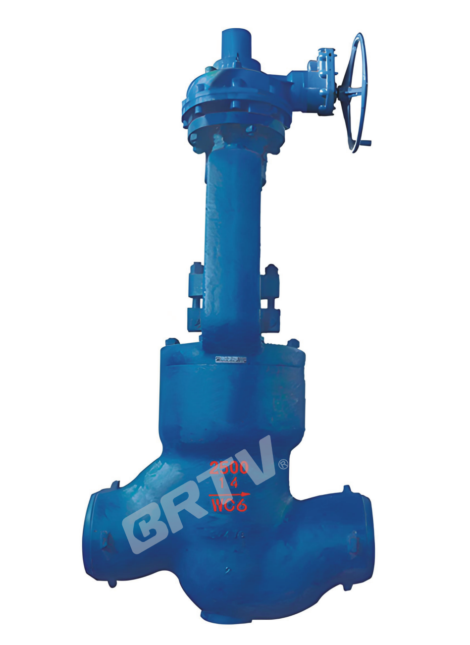
High Pressure Throttle Globe Valve
Product overview
This series of stop and throttle valves adopt the structure of self balance and floating seal seat, which has novel structure and reliable performance. It is suitable for water, oil with working pressure ≥ 1.6Mpa and working temperature ≤ 121℃. For mud, polymer, clay glue, natural gas and other pipelines, the flow rate of medium shall be accurately adjusted with the aid of flowmeter, and the stop valve can be used to open and close the pipeline at the same time.
Main Characteristics
- Adopt self balance structure, easy to operate.
- The valve rod has two kinds of structures: open rod and concealed rod. The concealed rod type has a switch indicator, which can adjust the flow intuitively.
- The valve rod seal adopts compound seal, reliable seal and small friction resistance.
- The sealing surface is spray welded with cemented carbide, which is corrosion-resistant, wear-resistant, erosion resistant and has a long service life.
- The valve is a fully enclosed structure, which prevents the external impurities from entering the inner cavity, effectively protects the internal parts and prolongs the service life of the valve.
Technical Specification
| Design standard | — | JB/T 12235, GB/T 12224 |
|---|
| Structural length | Flanged | GB/T 12221, ANSI B16.10 |
| Structural length | Welded connection | GB/T 15188.1 |
| Flanged ends | — | GB/T 9113, JB/T 79, ANSI 16.5a |
| Butt-welding ends | — | GB/T 12224 |
| Test & inspection | — | GB/T 3927, JB/T 9092 |
Products Performance Specification
| Scope of application | — | PN 10.0 ~ 42.0 MPa; DN 25 ~ 200 mm |
|---|
| Applicable temperature | — | -29 ~ 121°C |
| Applicable medium | Ordinary type | Petroleum, natural gas, readymade oil, water, etc. |
| Applicable medium | Antisulphur type | Petroleum, natural gas etc. containing H2S, CO2 |
| Connecting type | — | Flange end, welded end, keeper end |
| Driving manner | — | Manual, electric, pneumatic, etc. |
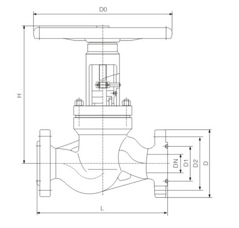
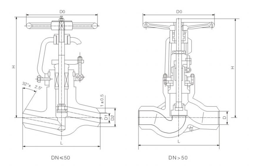
Main external and connection dimension
(mm)
| PN (MPa) | DN (mm) | L | DN1 | D | H | D0 |
|---|
| 16.0/20.0 | 25 | 216 | 23 | 42 | 300 | 200 |
| 16.0/20.0 | 32 | 229 | 29 | 54 | 325 | 240 |
| 16.0/20.0 | 40 | 241 | 36 | 60 | 355 | 240 |
| 16.0/20.0 | 50 | 280 | 45 | 73 | 395 | 300 |
| 16.0/20.0 | 65 | 330 | 58 | 89 | 425 | 320 |
| 16.0/20.0 | 80 | 368 | 72 | 108 | 460 | 360 |
| 16.0/20.0 | 100 | 457 | 90 | 133 | 508 | 400 |
| 16.0/20.0 | 125 | 533 | 115 | 152 | 530 | 500 |
| 16.0/20.0 | 150 | 610 | 135 | 194 | 650 | 550 |
| 16.0/20.0 | 200 | 660 | 180 | 245 | 690 | 600 |
| 25.0/35.0/45.0 | 25 | 216 | 23 | 42 | 300 | 200 |
| 25.0/35.0/45.0 | 32 | 229 | 29 | 54 | 325 | 240 |
| 25.0/35.0/45.0 | 40 | 241 | 36 | 60 | 355 | 240 |
| 25.0/35.0/45.0 | 50 | 280 | 45 | 73 | 395 | 300 |
| 25.0/35.0/45.0 | 65 | 330 | 58 | 89 | 425 | 320 |
| 25.0/35.0/45.0 | 80 | 368 | 72 | 108 | 460 | 360 |
| 25.0/35.0/45.0 | 100 | 457 | 90 | 133 | 508 | 400 |
| 25.0/35.0/45.0 | 125 | 633 | 115 | 152 | 530 | 500 |
| 25.0/35.0/45.0 | 150 | 610 | 135 | 194 | 650 | 550 |
High Temperature High Pressure Globe Valve
Application
High Temperature High Pressure Globe Valve for power station is suitable for temperature ≤540℃ P57/170V ≤570℃ PN10.0–45.0MPa, working for in the petroleum, chemical, fire power plant and other systems of the pipeline. Applicable medium: water, oil, steam, etc.
Structure and characteristic
1, Welded structure is used for the connection between valve and pipeline.
2, The sealing face is not easily worn out and scraped, of good sealing performance and long duration.
3, Compact structure, good open-close performance, short in height and easy maintenance.
4, Suitable for the water, steam, oil goods pipelines and featuring high temperature and high pressure resistance.
Main standards
| Design and Manufacture | Face to Face | Pressure & Temperature | Inspection and Test |
|---|
| E101, JB/T 3595, DL/T 531 | E101, JB 2766, GB/T 15188.1 | E101, JB/T 3595 | E101, JB/T 9092 |
Applicable Specifications
| Type | Nominal Pressure | Strength Test (MPa) | Seal Test (MPa) | Working Temperature (°C) | Suitable Medium |
|---|
| J61Y-250I / J961Y-250I | 25.0 | 37.5 | 27.5 | ≤550 | Water, steam, oil |
| J61Y-320I / J961Y-320I | 32.0 | 48.0 | 35.2 | ≤550 | Water, steam, oil |
| J61Y-P54100V / J961Y-P54100V | P54100V | 30.0 | 11.0 | ≤540 | Water, steam, oil |
| J61Y-P54140V / J961Y-P54140V | P54140V | 42.0 | 15.4 | ≤540 | Water, steam, oil |
| J61Y-P57170V / J961Y-P57170V | P57170V | 63.0 | 18.7 | ≤570 | Water, steam, oil |
Materials of main parts
| Part | Body | Bonnet | Stem | Disc | Sealing surface | Packing | Stem nut | Hand wheel | Fastener |
|---|
| J64 type | WCB (25) | 40Cr (25) | Stainless steel / Cr-MoAl steel nitration | Stainless steel | Stainless steel | — | — | — | High-grade carbon steel / Cr-Mo steel |
| J61Y type | WCB (25) | 40Cr (25) | Stainless steel / Cr-MoAl steel nitration | 25 | Carbide alloy | — | — | — | Cr-Mo steel |
| J61Y-P54 | ZG20CrMoV / 12Cr1Mo1V | 12Cr1Mo1V | 20Cr1Mo1VA / 25Cr2Mo1VA | 12Cr1Mo1V | Carbide alloy | Flexible graphite | Albronze | Forgeable cast iron | Cr-Mo steel |
| J61Y-P55 | ZG15CrMoV / 12Cr1Mo1V | 12Cr1Mo1V | 20Cr1Mo1VA / 25Cr2Mo1VA | 12Cr1Mo1V | Carbide alloy | Flexible graphite | — | — | Cr-Mo steel |
| J61Y-P57 | ZG15CrMoV / 12Cr1Mo1V | 12Cr1Mo1V | 20Cr1Mo1VA / 25Cr2Mo1VA | 12Cr1Mo1V | Carbide alloy | Flexible graphite | — | — | Cr-Mo steel |
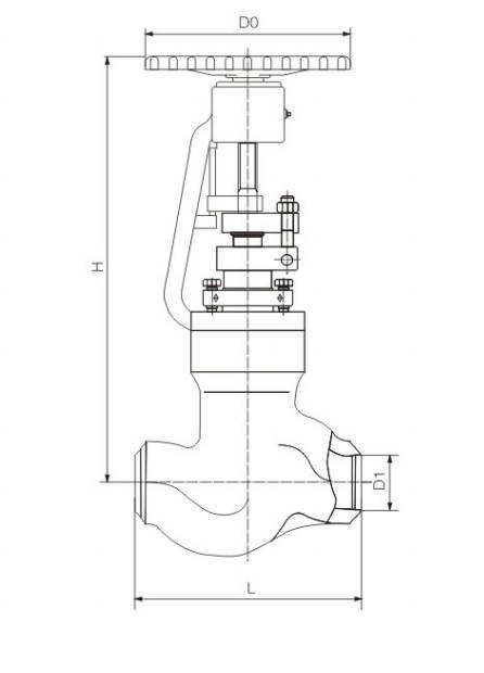
overall Size & Weight
J61Y–1500Lb
| Size (in) | L (mm) | d (mm) | H (mm) | D0 (mm) | Weight (kg) |
|---|
| 3 | 470 / 305 | 64 | 848 | 510 | 150 |
| 4 | 546 / 406 | 84 | 910 | 560 | 240 |
| 5 | 673 / 483 | 100 | 1030 | 610 | 251 |
J61Y–2000Lb / 2500Lb
| Size (in) | L (mm) | d (mm) | H (mm) | D0 (mm) | Weight (kg) |
|---|
| 2-1/2 | 508 / 330 | 50 / 46 | 815 / 857 | 510 | 160 / 250 |
| 3 | 578 / 368 | 60 / 54 | 895 / 940 | 560 | 200 / 290 |
| 4 | 673 / 457 | 80 / 70 | 1024 / 1085 | 700 | 280 / 325 |
J61Y–3500Lb
| Size (in) | L (mm) | d (mm) | H (mm) | D0 (mm) | Weight (kg) |
|---|
| 2-1/2 | 508 / 330 | 38 | 890 | 460 | 235 |
| 3 | 578 / 368 | 48 | 1030 | 560 | 425 |
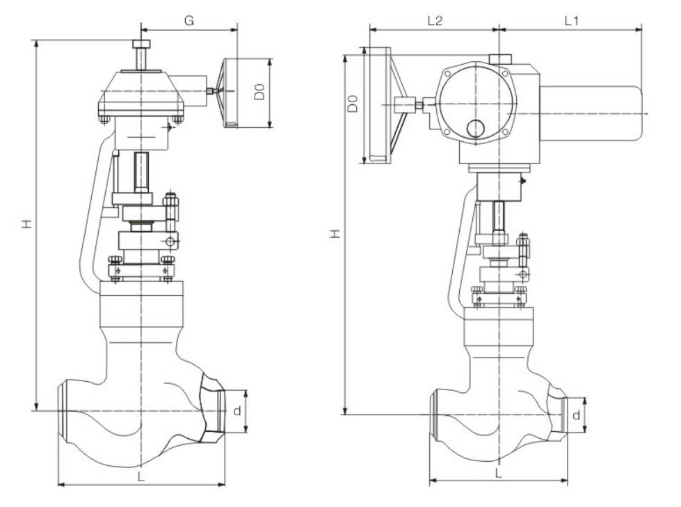
J561Y–1500Lb
| Size (in) | L (mm) | d (mm) | H (mm) | G (mm) | D0 (mm) | Gear box model | Weight (kg) |
|---|
| 5 | 673 / 483 | 100 | 995 | 332 | 460 | BA-1 | 303 |
| 5 | 673 / 483 | 100 | 1170 | 417 | 610 | BA-2 | 388 |
| 6 | 705 / 559 | 126 | 1360 | 332 | 460 | BA-1 | 680 |
| 8 | 832 / 711 | 158 | 1500 | 417 | 610 | BA-2 | 762 |
J561Y–2000Lb / 2500Lb
| Size (in) | L (mm) | d (mm) | H (mm) | G (mm) | D0 (mm) | Gear box model | Weight (kg) |
|---|
| 4 | 673 / 457 | 80 / 70 | 1125 / 1185 | 332 / 417 | 460 / 610 | BA-1 / BA-2 | 386 / 425 |
| 5 | 694 / 533 | 96 / 86 | 1370 / 1435 | 417 / 459 | 610 / 760 | BA-2 / BA-3 | 460 / 565 |
| 6 | 914 / 610 | 118 / 104 | 1430 / 1495 | 417 / 459 | 610 / 760 | BA-2 / BA-3 | 560 / 625 |
J961Y–3500Lb
| Size (in) | L (mm) | d (mm) | H (mm) | G (mm) | D0 (mm) | Gear box model | Weight (kg) |
|---|
| 3 | 578 | 48 | 1055 | 262 | 310 | BA-0 | 458 |
| 3 | 578 | 48 | 1050 | 332 | 460 | BA-1 | 477 |
| 4 | 673 | 60 | 1264 | 332 | 460 | BA-1 | 641 |
| 4 | 673 | 60 | 1335 | 417 | 610 | BA-2 | 680 |
| 5 | 794 | 74 | 1435 | 332 | 460 | BA-1 | 903 |
| 5 | 794 | 74 | 1500 | 417 | 610 | BA-2 | 940 |
| 6 | 914 | 88 | 1600 | 459 | 760 | BA-3 | 1050 |
PN 200 (P54/P55/P57 100V)
| DN (mm) | L (mm) | D1 | D2 | Do | H | H1 | L1 | Actuator type |
|---|
| 10 | 110 | 10 | 20 | 150 | 230 | 500 | 570 | Z5 |
| 15 | 110 | 13 | 28 | 150 | 230 | 500 | 570 | Z5 |
| 20 | 150 | 18 | 32 | 200 | 270 | 580 | 590 | Z10 |
| 25 | 180 | 23 | 36 | 250 | 320 | 590 | 590 | Z15 |
| 32 | 180 | 36 | 46 | 250 | 320 | 590 | 590 | Z15 |
| 40 | 250 | 41 | 52 | 250 | 480 | 720 | 590 | Z20 |
| 50 | 250 / 350 | 64 | 80 | 320 | 480 | 720 | 590 | Z30 |
| 65 | 420 | 75 | 92 | 400 | 610 | 820 | 810 | Z45 |
| 80 | 470 | 92 | 111 | 450 | 660 | 1160 | 810 | Z60 |
| 100 | 546 | 113 | 136 | 500 | 810 | 1315 | 830 | Z90 |
| 125 | 559 | 144 | 172 | 550 | 940 | 1480 | 830 | Z120 |
| 150 | 610 | 166 | 198 | 600 | 1040 | 1540 | 870 | Z180 |
PN 250 (P54/P55/P57 140V)
| DN (mm) | L (mm) | D1 | D2 | Do | H | H1 | L1 | Actuator type |
|---|
| 10 | 110 | 10 | 20 | 150 | 230 | 500 | 570 | Z5 |
| 15 | 110 | 13 | 28 | 150 | 230 | 500 | 570 | Z5 |
| 20 | 150 | 18 | 32 | 200 | 270 | 580 | 590 | Z10 |
| 25 | 180 | 23 | 36 | 250 | 320 | 590 | 590 | Z15 |
| 32 | 180 | 36 | 46 | 250 | 320 | 590 | 590 | Z15 |
| 40 | 250 | 41 | 52 | 250 | 480 | 720 | 590 | Z20 |
| 50 | 250 / 350 | 60 | 80 | 320 | 480 | 720 | 590 | Z30 |
| 65 | 420 | 70 | 92 | 400 | 610 | 820 | 810 | Z45 |
| 80 | 470 | 86 | 111 | 450 | 660 | 1160 | 810 | Z60 |
| 100 | 546 | 105 | 136 | 500 | 810 | 1315 | 830 | Z90 |
| 125 | 559 | 136 | 172 | 550 | 940 | 1480 | 830 | Z120 |
| 150 | 610 | 154 | 198 | 600 | 1040 | 1540 | 870 | Z180 |
PN 320 (P54/P55/P57 170V)
| DN (mm) | L (mm) | D1 | D2 | Do | H | H1 | L1 | Actuator type |
|---|
| 10 | 110 | 10 | 20 | 150 | 230 | 500 | 570 | Z5 |
| 15 | 110 | 13 | 28 | 150 | 230 | 500 | 570 | Z5 |
| 20 | 150 | 18 | 32 | 200 | 270 | 580 | 590 | Z10 |
| 25 | 180 | 23 | 36 | 250 | 320 | 590 | 590 | Z15 |
| 32 | 180 | 36 | 46 | 250 | 320 | 590 | 590 | Z15 |
| 40 | 250 | 41 | 52 | 250 | 480 | 720 | 590 | Z20 |
| 50 | 250 / 350 | 56 | 80 | 320 | 480 | 720 | 590 | Z30 |
| 65 | 420 | 67 | 92 | 400 | 610 | 820 | 810 | Z45 |
| 80 | 470 | 80 | 111 | 450 | 660 | 1160 | 810 | Z60 |
| 100 | 546 | 101 | 136 | 500 | 810 | 1315 | 830 | Z90 |
| 125 | 559 | 124 | 172 | 550 | 940 | 1480 | 830 | Z120 |
| 150 | 610 | 144 | 198 | 600 | 1040 | 1540 | 870 | Z180 |
Manufacturing Process
Step 1: Order and Design
According to the customer’s pressure class, size, material, and working conditions, the technical team confirms the design requirements of the high pressure globe valve. Drawings, material specifications, and production standards are then prepared before manufacturing begins.
Step 2: Forging & Casting
The main pressure-bearing parts such as body, bonnet, and disc are produced by forging or precision casting based on the valve design. For a high pressure globe valve, high-strength raw materials are selected to ensure excellent pressure resistance and structural reliability.
Step 3: Machining
All key components are machined with CNC lathes, drilling machines, and threading equipment. Special attention is given to sealing surfaces, stem threads, and body connection dimensions to guarantee the machining accuracy required for the high pressure globe valve.
Step 4: Assembly
After machining and inspection, all parts are assembled in sequence, including valve body, bonnet, stem, disc, seat, gasket, and handwheel. During this stage, the sealing performance and operating stability of the high pressure globe valve are carefully controlled.
Step 5: Testing & Quality Assurance
Each valve undergoes pressure testing, sealing testing, and visual inspection according to relevant standards. For every high pressure globe valve, strict quality control is applied to ensure safety, durability, and reliable performance under high-pressure service conditions.
Step 6: Painting and Finishing
After final inspection, the valve surface is cleaned, painted, and marked with product information such as size, pressure rating, heat number, and material grade. Proper finishing helps improve corrosion resistance and gives the valve a professional appearance before shipment.
Applications
Primarily used in high-pressure piping systems in industries such as petroleum, chemicals, and power generation, these valves are suitable for fully open or fully closed operations but are not suitable for flow control or high-viscosity media.
These valves are widely used in:
Agriculture and Irrigation
Factory Environment
Why Choose Us
Superior Quality

Our valves are manufactured using premium materials and undergo rigorous quality testing to ensure reliable performance in demanding industrial applications.
Advanced Technology

Equipped with state-of-the-art CNC machining centers and precision manufacturing equipment, we deliver valves with exceptional accuracy and consistency.
Competitive Pricing

Through optimized manufacturing processes and bulk material procurement, we offer high-quality valves at competitive prices without compromising on quality.
Expert Support

Our experienced technical team provides comprehensive support from product selection to after-sales service, ensuring optimal valve performance for your specific application.