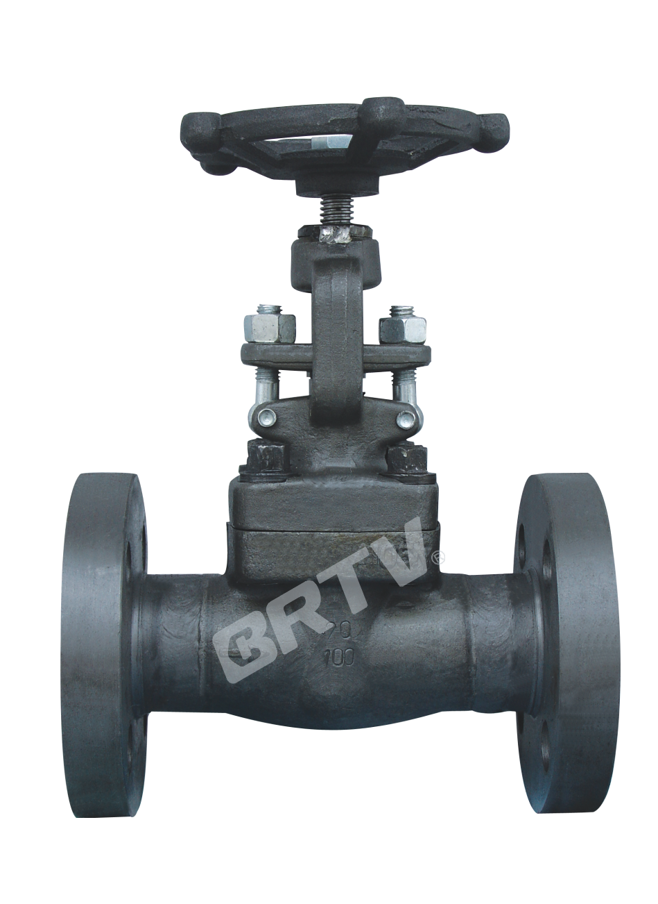
Application
Forged Steel Globe Valve valves are available in Three bonnet designs. The first design is the Bolted Bonnet, with male-Female joint, spiral wound gasket, made in F304+flexible graphite. Ring joint gasket are also available on request. The second design the welded bonnet, with a threaded and seal welded joint. On request a full penetration strength welded joint is available. The third design is the pressure seal bonnet, with a threaded and pressure seal bonnet joint.
Structure features
• Full port or reduced port;
• Outside screw and yoke (OS&Y);
• Two piece self-aligning packing gland;
• Bolted bonnet with spiral-wound gasket, threaded and seal welded bonnet or threaded and pressure seal bonnet;
• Integral backseat;
• Socket weld ends to ASME B16.11;
• Screwed ends(NPT) to ANSI/ASME B1.20.1;
• Disc can change for throttle type, needle type, all type and check type.
Design Construction
-
Structural formation: Bolt-jointed bonnet outside stem yoke structure (Pressure sealed)
-
Driving manner: Hand-operated
-
Design standard: ASME B16.34, BS 5352
-
Face to face: ASME B16.10
-
Flanged ends: ASME B16.5
-
Test & inspection: API 598
Notes: The sizes of valve connecting flange and butt-welding terminas can be designed according to customer's requirement.
Major Parts Material Form
| No. | Part name | Material |
|---|
| 1 | Flange | ASTM A105; ASTM A182-F11, F22, F5, F9; ASTM A182-F304, F316, F321, F304L, F316L |
| 2 | Body | ASTM A105; ASTM A182-F11, F22, F5, F9; ASTM A182-F304, F316, F321, F304L, F316L |
| 3 | — | ASTM A105; ASTM A182-F11, F22, F5, F9; ASTM A182-F304, F316, F321, F304L, F316L |
| 4 | Stem | ASTM A182 Gr.F6a, ASTM A182 F22; ASTM A182-F304, F316, F321, F304L, F316L |
| 5 | Gasket | Graphite & stainless steel |
| 6 | Bonnet | ASTM A105; ASTM A182-F11, F22, F5, F9; ASTM A182-F304, F316, F321, F304L, F316L |
| 7 | Bolt | ASTM A193-B7, A320-B8, A193-B8M |
| 8 | Packing | Graphite |
| 9 | Stuffing cover | ASTM A105; ASTM A182-F11, F22, F5, F9; ASTM A182-F304, F316, F321, F304L, F316L |
| 10 | Gland | ASTM A216-WCB; ASTM A351-CF8, CF8M, CF8C, CF3, CF3M |
| 11 | Valve stem nut | Copper alloy |
| 12 | Handwheel | ASTM A47-32510 |
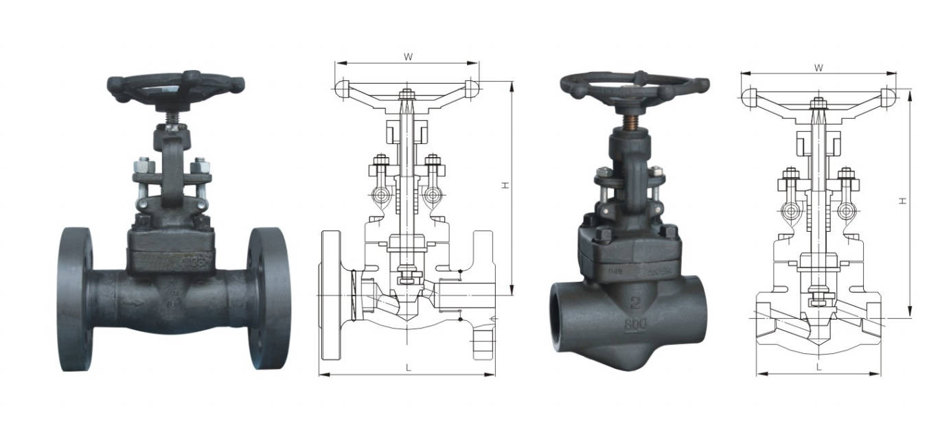
Main Size of Outside & Weight
Class 150 / 300 / 600
| DN (mm) | DN (in) | Class | L (RF) | L (RTJ) | H | W | Weight (kg) |
|---|
| 15 | 1/2 | 150 | 108 | 119 | 170 | 100 | 3.5 |
| 15 | 1/2 | 300 | 152.5 | 163.5 | 170 | 100 | 4.2 |
| 15 | 1/2 | 600 | 165 | 163.5 | 170 | 100 | 5.5 |
| 20 | 3/4 | 150 | 117 | 130 | 170 | 100 | 4.8 |
| 20 | 3/4 | 300 | 178 | 191 | 170 | 100 | 5.3 |
| 20 | 3/4 | 600 | 190.5 | 190.5 | 170 | 100 | 7.0 |
| 25 | 1 | 150 | 127 | 140 | 205 | 125 | 6.5 |
| 25 | 1 | 300 | 203 | 216 | 205 | 125 | 7.5 |
| 25 | 1 | 600 | 216 | 216 | 205 | 125 | 9.7 |
| 32 | 1-1/4 | 150 | 140 | 153 | 225 | 160 | 9.8 |
| 32 | 1-1/4 | 300 | 216 | 229 | 225 | 160 | 11.3 |
| 32 | 1-1/4 | 600 | 229 | 229 | 225 | 160 | 12.5 |
| 40 | 1-1/2 | 150 | 165 | 178 | 254 | 160 | 12 |
| 40 | 1-1/2 | 300 | 228.5 | 241 | 254 | 160 | 16.5 |
| 40 | 1-1/2 | 600 | 241 | 241 | 254 | 160 | 18.4 |
| 50 | 2 | 150 | 203 | 216 | 292 | 180 | 15 |
| 50 | 2 | 300 | 266.5 | 282 | 292 | 180 | 18.2 |
| 50 | 2 | 600 | 292 | 295 | 292 | 180 | 20 |
Class 900 / 1500 / 2500
| DN (mm) | DN (in) | Full bore (mm/in) | Class | L | H | W | Weight (kg) |
|---|
| 15 | 1/2 | 10 / 3/8 | 900 | 80 | 170 | 100 | 1.9 |
| 15 | 1/2 | 10 / 3/8 | 1500 | 111 | 205 | 125 | 4.5 |
| 15 | 1/2 | 10 / 3/8 | 2500 | 111 | 190 | 125 | 4.5 |
| 20 | 3/4 | 15 / 1/2 | 900 | 92 | 170 | 100 | 2.1 |
| 20 | 3/4 | 15 / 1/2 | 1500 | 111 | 205 | 125 | 4.3 |
| 20 | 3/4 | 15 / 1/2 | 2500 | 127 | 225 | 140 | 5.5 |
| 25 | 1 | 20 / 3/4 | 900 | 111 | 205 | 125 | 3.2 |
| 25 | 1 | 20 / 3/4 | 1500 | 130 | 240 | 160 | 6.8 |
| 25 | 1 | 20 / 3/4 | 2500 | 127 | 246 | 160 | 8.0 |
| 32 | 1-1/4 | 25 / 1 | 900 | 120 | 225 | 160 | 6.9 |
| 32 | 1-1/4 | 25 / 1 | 1500 | 150 | 258 | 160 | 8.5 |
| 32 | 1-1/4 | 25 / 1 | 2500 | 160 | 287 | 160 | 13.2 |
| 40 | 1-1/2 | 32 / 1-1/4 | 900 | 120 | 254 | 160 | 6.9 |
| 40 | 1-1/2 | 32 / 1-1/4 | 1500 | 172 | 290 | 160 | 12.6 |
| 40 | 1-1/2 | 32 / 1-1/4 | 2500 | 180 | 290 | 180 | 12.8 |
| 50 | 2 | 40 / 1-1/2 | 900 | 140 | 292 | 180 | 10.4 |
| 50 | 2 | 40 / 1-1/2 | 1500 | 220 | 336 | 180 | 19.2 |
| 50 | 2 | 40 / 1-1/2 | 2500 | 210 | 362 | 200 | 19.8 |
| 50 | 2 | 50 / 2 | 900 | 178 | 330 | 240 | 15.8 |
| 50 | 2 | 50 / 2 | 1500 | 230 | 428 | 234 | 30 |
| 50 | 2 | 50 / 2 | 2500 | 230 | 420 | 240 | 30 |
Manufacturing Process
Step 1: Order and Design
According to customer requirements, the forged steel globe valve is confirmed in terms of size, pressure class, material, connection type, and applicable standards. Then technical drawings and production plans are prepared to ensure the valve structure and dimensions meet the project specifications.
Step 2: Forging & Casting
The main pressure-bearing parts of the forged steel globe valve, such as body, bonnet, and disc, are produced from high-quality forged steel materials. Forging improves the mechanical strength and internal density of the components, making the valve suitable for high-pressure and high-temperature working conditions.
Step 3: Machining
After forging, all valve components go through precision machining, including turning, drilling, threading, sealing surface machining, and flange finishing. This step is critical to ensure the forged steel globe valve has accurate dimensions, smooth sealing surfaces, and reliable shut-off performance.
Step 4: Assembly
All finished parts are carefully cleaned and assembled, including the body, bonnet, stem, disc, seat, gasket, and handwheel. During assembly, special attention is paid to sealing alignment and stem operation, so that the forged steel globe valve can open and close smoothly.
Step 5: Testing & Quality Assurance
Each forged steel globe valve is subjected to strict inspection and testing, such as shell pressure test, seat leakage test, dimension inspection, and visual examination. These procedures ensure the valve meets international standards and quality requirements before delivery.
Step 6: Painting and Finishing
After testing, the valve surface is cleaned, anti-rust treated, and coated if required. Finally, marking, packing, and final inspection are completed to ensure the product is ready for shipment in good condition.
Applications
Suitable for water, steam, oils, and corrosive media; operating temperature range: -29°C to 550°C.
These valves are widely used in:
Agriculture and Irrigation
Factory Environment
Why Choose Us
Superior Quality

Our valves are manufactured using premium materials and undergo rigorous quality testing to ensure reliable performance in demanding industrial applications.
Advanced Technology

Equipped with state-of-the-art CNC machining centers and precision manufacturing equipment, we deliver valves with exceptional accuracy and consistency.
Competitive Pricing

Through optimized manufacturing processes and bulk material procurement, we offer high-quality valves at competitive prices without compromising on quality.
Expert Support

Our experienced technical team provides comprehensive support from product selection to after-sales service, ensuring optimal valve performance for your specific application.