Product Overview
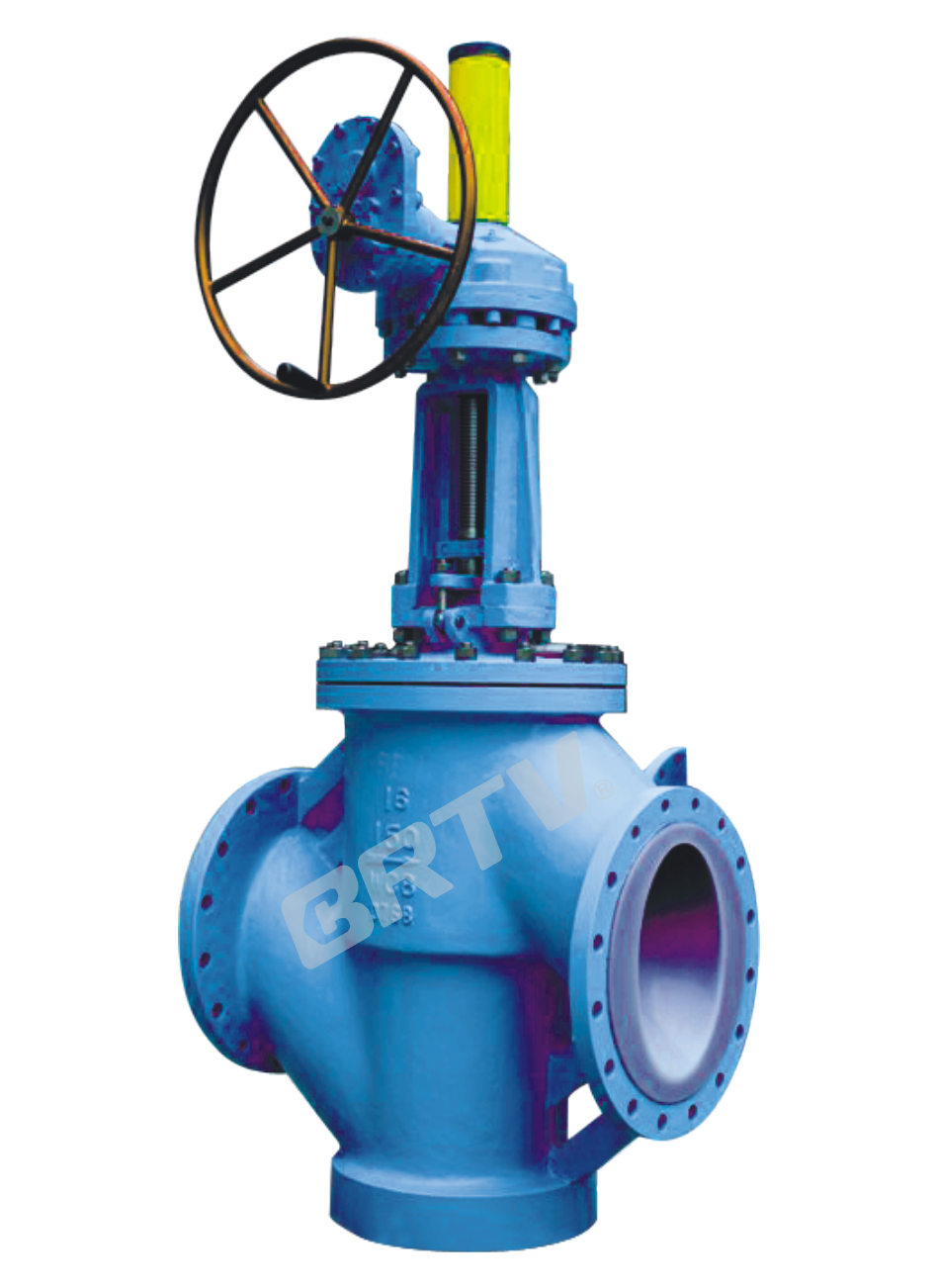
Fluorine Lined Globe Valve produced by our company feature a disc that moves up and down along the center line of the seat driven by the stem. They are used for connecting or shutting off the medium and are not suitable for regulating flow.
Product Feature
• Fully lined fluoroplastic through-way type J41F46, Y type J45F46, and J44F46 angle globe valves are widely used in oil, chemical, and industrial pipeline systems for shut-off functions. They offer a compact structure, flexible opening and closing, good erosion resistance, and a short flow path. However, globe valves cannot be used for flow regulation, as high-speed medium flow may damage and erode the sealing surface.
• The disc and stem are designed as an integrated structure to prevent internal parts from being forced out of the valve due to pressure waves.
Executive Standard
| Design and manufacture | GB 12233 / GB 12235 |
|---|
| Face to face | GB 12221 (Short–long pattern series) |
| Flange dimension | JB78 / JB79 (or according to contract) |
| Pressure test | GB/T 13927 |
| Symbol | GB 12220 |
| Supply | GB/T 12252 |
Main part material Specifications
| No. | Part name | Grey cast iron (Z) | Carbon steel (C) | Stainless steel (P) | Stainless steel (R) | Low carbon SS (PL) | Low carbon SS (RL) |
|---|
| 1 | Body, Bonnet | HT250 | WCB | CF8 | CF8M | CF3 | CF3M |
| 2 | Disc, Stem | 35 | 1Cr13 | 1Cr18Ni9 | 1Cr18Ni12Mo2Ti | 00Cr18Ni10 | 00Cr17Ni14Mo2 |
| 3 | Swing bolt | 35 | 35 | 1Cr17Ni2 | 1Cr17Ni2 | 1Cr17Ni2 | 1Cr17Ni2 |
| 4 | Lining / Seat | FEP (F46), PCTFE (F3), PFA, PO (material-dependent) | | | | | |
| 5 | Packing | PTFE (F4) (common for all materials) | | | | | |
| 6 | Packing gland | WCB | WCB | CF8 | CF8M | CF3 | CF3M |
| 7 | Stem nuts | ZCuAl10Fe3 | ZCuAl10Fe3 | — | — | — | — |
| 8 | Bolt | 35 | 35CrMoA | 1Cr17Ni2 | 1Cr17Ni2 | 1Cr18Ni9Ti | 1Cr18Ni9Ti |
| 9 | Nuts | 45 | 45 | 0Cr18Ni9 | 0Cr18Ni9 | 0Cr18Ni9 | 0Cr18Ni9 |
| 10 | Handwheel | HT200 | HT200 | WCC | WCC | WCC | WCC |
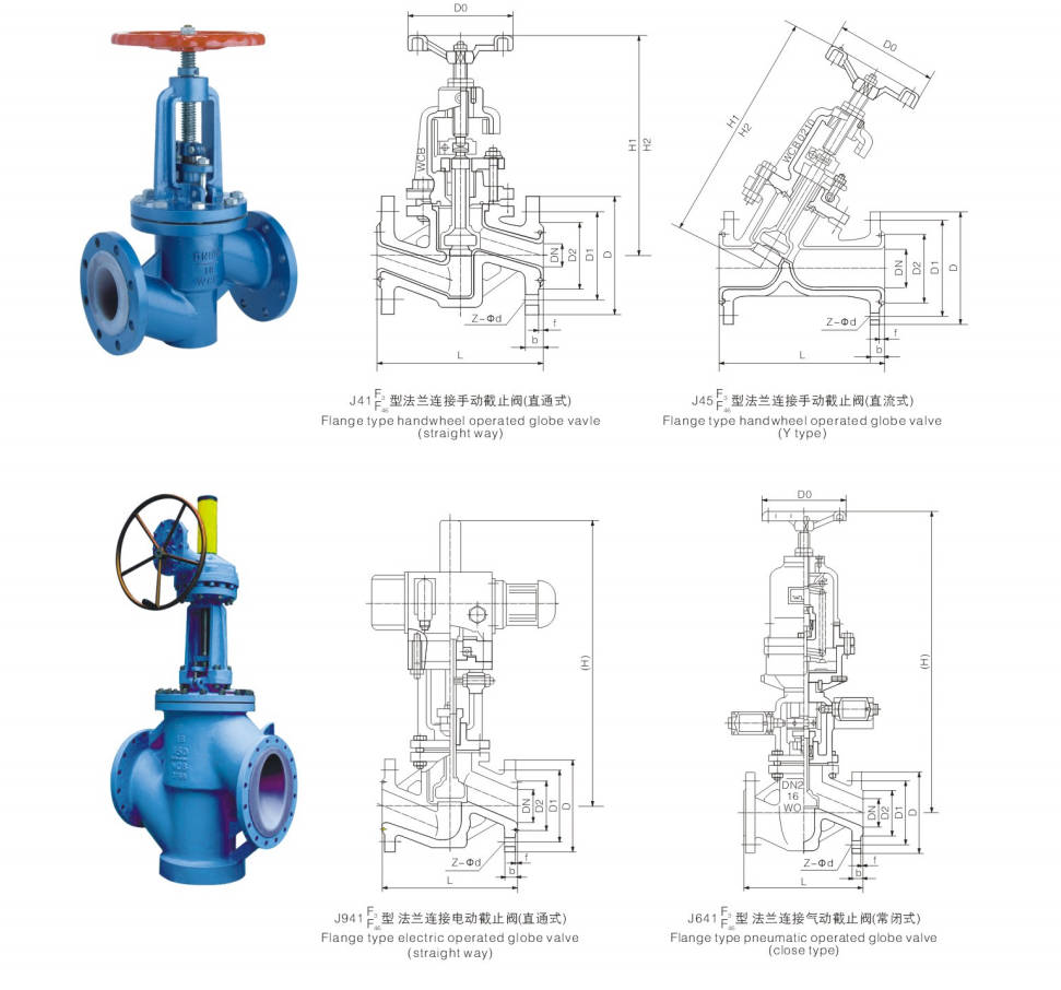
Basic Type
| Operation Type | Model |
|---|
| Manually | J41F₃ / J41F₄₆ / J45F₃ / J45F₄₆ |
| Gear operated | J541F₃ / J541F₄₆ |
| Pneumatic | J641F₃ / J6B41F₄₆ |
| Electric | J941F₃ / J941F₄₆ |
Main Dimension
PN1.0 (MPa)
| DN (mm) | NPS (inch) | L | D | D1 | D2 | f | b | Z-φd | Do | H1 | H2 | W (kg) |
|---|
| 15 | 1/2 | 130 | 95 | 65 | 45 | 2 | 14 | 4-φ14 | 100 | 235 | 260 | 6.5 |
| 20 | 3/4 | 150 | 105 | 75 | 55 | 2 | 16 | 4-φ14 | 100 | 240 | 265 | 7 |
| 25 | 1 | 160 | 115 | 85 | 65 | 2 | 16 | 4-φ14 | 120 | 245 | 270 | 7.8 |
| 32 | 1 1/4 | 180 | 135 | 100 | 78 | 2 | 18 | 4-φ18 | 140 | 255 | 285 | 11 |
| 40 | 1 1/2 | 200 | 145 | 110 | 85 | 3 | 18 | 4-φ18 | 140 | 285 | 315 | 13 |
| 50 | 2 | 230 | 160 | 125 | 100 | 3 | 20 | 4-φ18 | 160 | 295 | 330 | 15 |
| 65 | 2 1/2 | 290 | 180 | 145 | 120 | 3 | 20 | 4-φ18 | 180 | 350 | 395 | 23 |
| 80 | 3 | 310 | 195 | 160 | 135 | 3 | 22 | 4/8-φ18 | 240 | 395 | 445 | 38 |
| 100 | 4 | 350 | 215 | 180 | 155 | 3 | 22 | 8-φ18 | 240 | 450 | 490 | 42 |
| 125 | 5 | 400 | 245 | 210 | 185 | 3 | 24 | 8-φ18 | 280 | 525 | 555 | 55 |
| 150 | 6 | 480 | 280 | 240 | 210 | 3 | 24 | 8-φ23 | 320 | 605 | 645 | 77 |
| 200 | 8 | 495 | 335 | 295 | 265 | 3 | 26 | 8-φ23 | 360 | 645 | 765 | 135 |
| 250 | 10 | 622 | 390 | 350 | 320 | 3 | 28 | 12-φ23 | 400 | 685 | 805 | 220 |
| 300 | 12 | 698 | 440 | 400 | 368 | 4 | 28 | 12-φ23 | 400 | 710 | 814 | 277 |
| 350 | 14 | 787 | 500 | 460 | 428 | 4 | 30 | 16-φ23 | 450 | 750 | 855 | 320 |
PN1.6 (MPa)
| DN | NPS | L | D | D1 | D2 | f | b | Z-φd | Do | H1 | H2 | W |
|---|
| 15 | 1/2 | 130 | 95 | 65 | 45 | 2 | 14 | 4-φ14 | 100 | 240 | 265 | 7 |
| 20 | 3/4 | 150 | 105 | 75 | 55 | 2 | 16 | 4-φ14 | 100 | 245 | 270 | 7.6 |
| 25 | 1 | 160 | 115 | 85 | 65 | 2 | 16 | 4-φ14 | 120 | 250 | 275 | 8.2 |
| 32 | 1 1/4 | 180 | 135 | 100 | 78 | 2 | 18 | 4-φ18 | 140 | 260 | 290 | 12 |
| 40 | 1 1/2 | 200 | 145 | 110 | 85 | 3 | 18 | 4-φ18 | 140 | 285 | 320 | 14 |
| 50 | 2 | 230 | 160 | 125 | 100 | 3 | 20 | 4-φ18 | 160 | 300 | 335 | 18 |
| 65 | 2 1/2 | 290 | 180 | 145 | 120 | 3 | 20 | 4-φ18 | 180 | 355 | 400 | 26 |
| 80 | 3 | 310 | 195 | 160 | 135 | 3 | 22 | 8-φ18 | 240 | 400 | 450 | 40 |
| 100 | 4 | 350 | 215 | 180 | 155 | 3 | 24 | 8-φ18 | 240 | 455 | 495 | 50 |
| 125 | 5 | 400 | 245 | 210 | 185 | 3 | 26 | 8-φ18 | 280 | 530 | 560 | 65 |
| 150 | 6 | 480 | 280 | 240 | 210 | 3 | 28 | 8-φ23 | 320 | 610 | 650 | 85 |
| 200 | 8 | 495 | 335 | 295 | 265 | 3 | 30 | 12-φ23 | 360 | 650 | 770 | 150 |
| 250 | 10 | 622 | 405 | 355 | 320 | 3 | 32 | 12-φ25 | 400 | 690 | 810 | 245 |
| 300 | 12 | 698 | 460 | 410 | 375 | 4 | 34 | 12-φ25 | 400 | 730 | 845 | 295 |
PN2.5 (MPa)
| DN | NPS | L | D | D1 | D2 | f | b | Z-φd | Do | H1 | H2 | W |
|---|
| 15 | 1/2 | 130 | 95 | 65 | 45 | 2 | 16 | 4-φ14 | 120 | 240 | 265 | 7.5 |
| 20 | 3/4 | 150 | 105 | 75 | 55 | 2 | 16 | 4-φ14 | 120 | 245 | 270 | 8 |
| 25 | 1 | 160 | 115 | 85 | 65 | 2 | 18 | 4-φ14 | 140 | 250 | 275 | 9 |
| 32 | 1 1/4 | 180 | 135 | 100 | 78 | 2 | 18 | 4-φ18 | 160 | 260 | 290 | 13 |
| 40 | 1 1/2 | 200 | 145 | 110 | 85 | 3 | 18 | 4-φ18 | 180 | 285 | 320 | 15 |
| 50 | 2 | 230 | 160 | 125 | 100 | 3 | 20 | 4-φ18 | 180 | 300 | 335 | 20 |
| 65 | 2 1/2 | 290 | 180 | 145 | 120 | 3 | 22 | 8-φ18 | 240 | 355 | 400 | 28 |
| 80 | 3 | 310 | 195 | 160 | 135 | 3 | 22 | 8-φ18 | 280 | 400 | 450 | 42 |
| 100 | 4 | 350 | 230 | 190 | 160 | 3 | 24 | 8-φ23 | 320 | 455 | 495 | 57 |
| 125 | 5 | 400 | 270 | 220 | 188 | 3 | 28 | 8-φ25 | 320 | 530 | 560 | 71 |
| 150 | 6 | 480 | 300 | 250 | 218 | 3 | 30 | 8-φ25 | 360 | 610 | 650 | 90 |
Manufacturing Process
Step 1: Order and Design
Based on the pressure rating, nominal diameter, connection type, and service conditions provided by the customer, we confirm the structural configuration, fluorine-lined material, valve body dimensions, and sealing requirements for the fluorine-lined globe valve. We then finalize the design drawings, bill of materials, and manufacturing process to prepare for subsequent production.
Step 2: Forging & Casting
In accordance with design requirements, major pressure-bearing components such as the valve body and bonnet are cast or forged. After the raw valve body blank is formed, it undergoes sand removal, grinding, and a preliminary visual inspection to ensure the casting is free of obvious defects such as shrinkage cavities, cracks, and porosity.
Step 3: Machining
Machining is performed on components such as the valve body, bonnet, stem, and flange sealing surfaces, including turning, drilling, boring, tapping, and finishing of sealing surfaces. During the machining process of the fluorine-lined globe valve, dimensional tolerances and fit accuracy must be strictly controlled to ensure the quality of subsequent lining and assembly.
Step 4: Assembly
After parts pass inspection, the fluorine lining process is performed, followed by full valve assembly, including the installation of the valve seat, disc, stem, packing, actuator, or handwheel. During the assembly of the fluorine-lined globe valve, special attention should be paid to verifying the integrity of the fluorine lining and ensuring smooth opening and closing operations as well as reliable sealing.
Step 5: Testing & Quality Assurance
After assembly, the fluorine-lined globe valve undergoes body strength testing, seal testing, operational testing, and visual inspection. If necessary, the adhesion of the lining and corrosion resistance are also checked to ensure the product meets relevant standards and customer requirements.
Step 6: Painting and Finishing
After passing the tests, the valve’s exterior is treated with rust removal, spray painting, labeling, and final packaging. Prior to shipment, nameplate verification, flange protection, and overall cleaning are completed to ensure the product’s appearance is neat, transportation is safe, and delivery requirements are met.
Applications
It is suitable for media such as aqua regia, sulfuric acid, hydrochloric acid, hydrofluoric acid, organic acids, strong acids, strong oxidizing agents, and strong alkaline organic solvents within a temperature range of -50°C to 150°C, and is widely used in the chemical, petroleum, and pharmaceutical industries.
These valves are widely used in:
Agriculture and Irrigation
Factory Environment
Why Choose Us
Superior Quality

Our valves are manufactured using premium materials and undergo rigorous quality testing to ensure reliable performance in demanding industrial applications.
Advanced Technology

Equipped with state-of-the-art CNC machining centers and precision manufacturing equipment, we deliver valves with exceptional accuracy and consistency.
Competitive Pricing

Through optimized manufacturing processes and bulk material procurement, we offer high-quality valves at competitive prices without compromising on quality.
Expert Support

Our experienced technical team provides comprehensive support from product selection to after-sales service, ensuring optimal valve performance for your specific application.