Product Overview
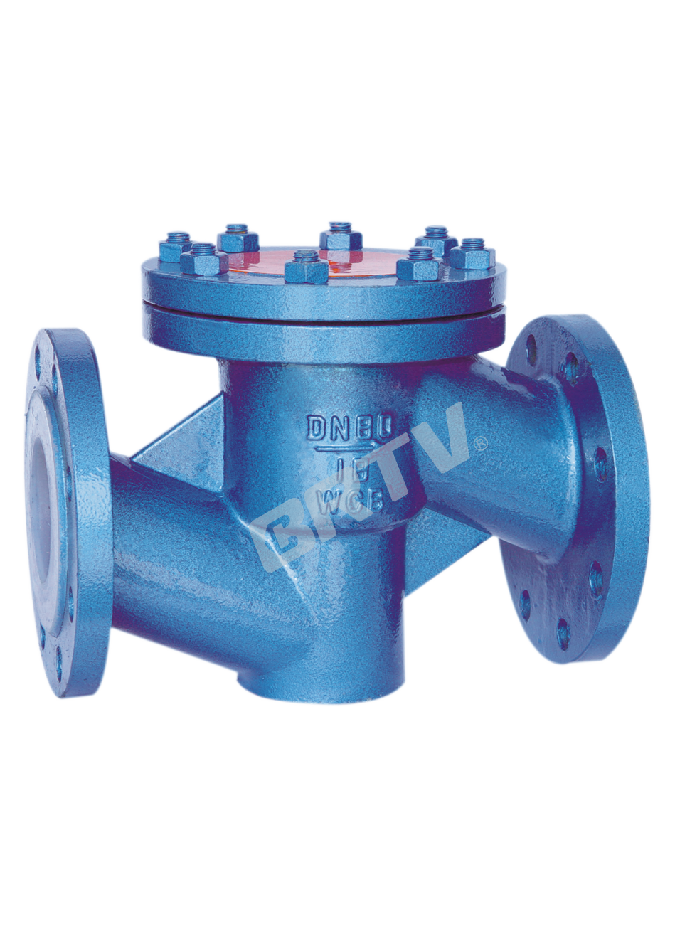
Fluorine lined check valve is a type of automatic valve that relies on the flow of the medium itself to open and close the valve disc automatically, preventing backflow of the medium.
Product Features
• The types of swing check valves include H44F46 and H74F46 fully lined single-disc swing series, and H76F46 double-disc swing series. These valves rotate and open/close around the axis outside the seat to prevent backflow. The H44F46 and H74F46 types feature an integrated shaft and disc, with the shaft fully lined with FEP and embedded in a special groove between the body and bonnet, allowing flexible operation and reliable sealing. The H72F46 and H76F46 types have the body, disc, and return spring fully lined with corrosion-resistant fluoroplastics. The spring is reasonably designed to ensure sufficient sealing pressure at low pressure, guaranteeing sealing performance.
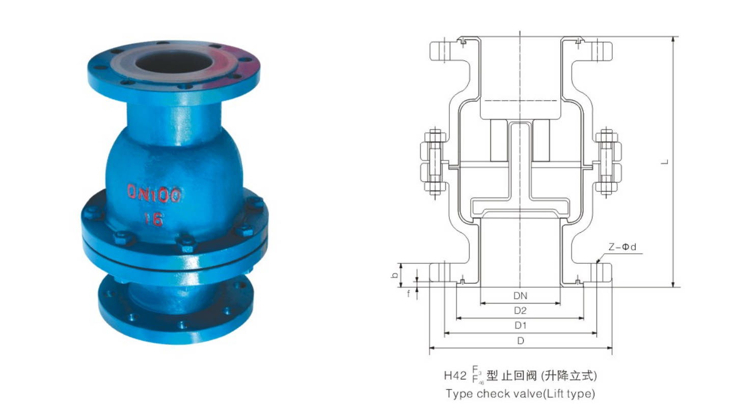
• Lift check valve: main types include H40F46, H42F46, and H72F46. Among them, H40F46 is a newer type with a semi-ball disc design. A common feature is that the fluoroplastic-lined disc moves up and down along the valve axis.
• The main type of lifting check valve is the fully lined H41F46 lifting check valve, characterized by a fluoroplastic-lined disc that moves vertically along the axis of the inlet.
Executive Standard
| Design and manufacture | GB 12239 |
|---|
| Face to face | GB/T 12221 |
| Flange dimension | JB 78 (or according to contract) |
| Pressure test | GB/T 13927 |
| Symbol | GB 12220 |
| Supply | GB/T 12252 |
Main Parts Material Specifications
| No. | Parts name | Grey cast iron (Z) | Carbon steel (C) | Stainless steel (P) | Stainless steel (R) | Low carbon SS (PL) | Low carbon SS (RL) |
|---|
| 1 | Body, Bonnet | HT250 | WCB | CF8 | CF8M | CF3 | CF3M |
| 2 | Lining / Seat | — | FEP (F46) | PCTFE (F3) | PFA | PO | — |
| 3 | Shaft, Wedge | — | 1Cr13 / 35 / WCB | 1Cr18Ni9 / CF8 | 00Cr17Ni14Mo2 / CF3M | — | — |
| 4 | Bolt | 35 | 35 | 1Cr17Ni2 | 1Cr17Ni2 | 1Cr18Ni9Ti | 1Cr18Ni9Ti |
| 5 | Nut | 45 | 45 | 0Cr18Ni9 | 0Cr18Ni9 | 0Cr18Ni9 | 0Cr18Ni9 |

Main Dimension
PN0.6 (MPa)
| DN | NPS | L | D | D1 | D2 | f | b | Z-φd | B | H | W (kg) |
|---|
| 15 | 1/2 | 130 | 80 | 55 | 40 | 2 | 12 | 4-φ12 | 105 | 55 | 4 |
| 20 | 3/4 | 150 | 90 | 65 | 50 | 2 | 14 | 4-φ12 | 115 | 58 | 5 |
| 25 | 1 | 160 | 100 | 75 | 60 | 2 | 14 | 4-φ12 | 128 | 60 | 6 |
| 32 | 1 1/4 | 180 | 120 | 90 | 70 | 2 | 16 | 4-φ14 | 145 | 75 | 7 |
| 40 | 1 1/2 | 200 | 130 | 100 | 80 | 3 | 16 | 4-φ14 | 160 | 82 | 8 |
| 50 | 2 | 230 | 140 | 110 | 90 | 3 | 16 | 4-φ14 | 178 | 95 | 10 |
| 65 | 2 1/2 | 290 | 160 | 130 | 110 | 3 | 16 | 4-φ14 | 205 | 105 | 20 |
| 80 | 3 | 310 | 185 | 150 | 125 | 3 | 18 | 4-φ18 | 230 | 120 | 25 |
| 100 | 4 | 350 | 205 | 170 | 145 | 3 | 18 | 4-φ18 | 255 | 135 | 30 |
| 125 | 5 | 400 | 235 | 200 | 175 | 3 | 20 | 8-φ18 | 305 | 158 | 50 |
| 150 | 6 | 480 | 260 | 225 | 200 | 3 | 20 | 8-φ18 | 345 | 180 | 65 |
| 200 | 8 | 495 | 315 | 280 | 255 | 3 | 22 | 8-φ18 | 415 | 215 | 137 |
| 250 | 10 | 622 | 370 | 335 | 310 | 3 | 24 | 12-φ18 | 490 | 240 | 150 |
| 300 | 12 | 698 | 435 | 395 | 362 | 4 | 24 | 12-φ23 | 540 | 265 | 185 |
| 350 | 14 | 787 | 485 | 445 | 412 | 4 | 26 | 12-φ23 | 585 | 300 | 215 |
| 400 | 16 | 914 | 535 | 495 | 462 | 4 | 28 | 16-φ23 | 635 | 360 | 244 |
| 450 | 18 | 978 | 590 | 550 | 518 | 4 | 28 | 16-φ23 | 680 | 385 | 276 |
| 500 | 20 | 978 | 640 | 600 | 568 | 4 | 30 | 16-φ23 | 740 | 415 | 315 |
PN1.0 (MPa)
| DN | NPS | L | D | D1 | D2 | f | b | Z-φd | B | H | W (kg) |
|---|
| 15 | 1/2 | 130 | 95 | 65 | 45 | 2 | 14 | 4-φ14 | 105 | 55 | 5 |
| 20 | 3/4 | 150 | 105 | 75 | 55 | 2 | 16 | 4-φ14 | 115 | 58 | 7 |
| 25 | 1 | 160 | 115 | 85 | 65 | 2 | 16 | 4-φ14 | 128 | 60 | 9 |
| 32 | 1 1/4 | 180 | 135 | 100 | 78 | 2 | 18 | 4-φ18 | 145 | 75 | 11 |
| 40 | 1 1/2 | 200 | 145 | 110 | 85 | 3 | 18 | 4-φ18 | 160 | 82 | 13.5 |
| 50 | 2 | 230 | 160 | 125 | 100 | 3 | 20 | 4-φ18 | 178 | 95 | 18 |
| 65 | 2 1/2 | 290 | 180 | 145 | 120 | 3 | 20 | 4-φ18 | 205 | 105 | 22 |
| 80 | 3 | 310 | 195 | 160 | 135 | 3 | 22 | 4/8-φ18 | 230 | 120 | 28 |
| 100 | 4 | 350 | 215 | 180 | 155 | 3 | 22 | 8-φ18 | 255 | 135 | 34 |
| 125 | 5 | 400 | 245 | 210 | 185 | 3 | 24 | 8-φ18 | 305 | 158 | 58 |
| 150 | 6 | 480 | 280 | 240 | 210 | 3 | 24 | 8-φ23 | 345 | 180 | 72 |
| 200 | 8 | 495 | 335 | 295 | 265 | 3 | 26 | 8-φ23 | 415 | 215 | 150 |
| 250 | 10 | 622 | 390 | 350 | 320 | 3 | 28 | 12-φ23 | 490 | 240 | 165 |
| 300 | 12 | 698 | 440 | 400 | 368 | 4 | 28 | 12-φ23 | 540 | 265 | 190 |
| 350 | 14 | 787 | 500 | 460 | 428 | 4 | 30 | 16-φ23 | 585 | 300 | 225 |
| 400 | 16 | 914 | 565 | 515 | 482 | 4 | 32 | 16-φ25 | 635 | 360 | 254 |
| 450 | 18 | 978 | 615 | 565 | 532 | 4 | 32 | 20-φ25 | 680 | 385 | 285 |
| 500 | 20 | 978 | 670 | 620 | 585 | 4 | 34 | 20-φ25 | 740 | 415 | 333 |
PN1.6 (MPa)
| DN | NPS | L | D | D1 | D2 | f | b | Z-φd | B | H | W (kg) |
|---|
| 15 | 1/2 | 130 | 95 | 65 | 45 | 2 | 14 | 4-φ14 | 110 | 55 | 6 |
| 20 | 3/4 | 150 | 105 | 75 | 55 | 2 | 16 | 4-φ14 | 120 | 58 | 7.8 |
| 25 | 1 | 160 | 115 | 85 | 65 | 2 | 16 | 4-φ14 | 135 | 60 | 10 |
| 32 | 1 1/4 | 180 | 135 | 100 | 78 | 2 | 18 | 4-φ18 | 150 | 75 | 12.5 |
| 40 | 1 1/2 | 200 | 145 | 110 | 85 | 3 | 18 | 4-φ18 | 165 | 82 | 14.5 |
| 50 | 2 | 230 | 160 | 125 | 100 | 3 | 20 | 4-φ18 | 185 | 95 | 19.5 |
| 65 | 2 1/2 | 290 | 180 | 145 | 120 | 3 | 20 | 4-φ18 | 210 | 105 | 25.5 |
| 80 | 3 | 310 | 195 | 160 | 135 | 3 | 22 | 8-φ18 | 235 | 120 | 30 |
| 100 | 4 | 350 | 215 | 180 | 155 | 3 | 24 | 8-φ18 | 260 | 135 | 36 |
| 125 | 5 | 400 | 245 | 210 | 185 | 3 | 26 | 8-φ18 | 310 | 158 | 62 |
| 150 | 6 | 480 | 280 | 240 | 210 | 3 | 28 | 8-φ23 | 350 | 180 | 78 |
| 200 | 8 | 495 | 335 | 295 | 265 | 3 | 30 | 12-φ23 | 420 | 215 | 156 |
| 250 | 10 | 622 | 405 | 355 | 320 | 3 | 32 | 12-φ25 | 505 | 240 | 172 |
| 300 | 12 | 698 | 460 | 410 | 375 | 4 | 34 | 12-φ25 | 560 | 265 | 240 |
| 350 | 14 | 787 | 520 | 470 | 435 | 4 | 38 | 16-φ25 | 605 | 300 | 208 |
| 400 | 16 | 914 | 580 | 525 | 485 | 4 | 40 | 16-φ30 | 650 | 350 | 265 |
Executive Standard
| Item | Standard / Specification |
|---|
| Design and manufacture | GB 12235 |
| Face to face | Enterprise standard |
| Flange dimension | JB 78 / JB79 (or according to contract) |
| Pressure test | GB/T 13927 |
| Symbol | GB 12220 |
| Supply | GB/T 12252 |
Main Dimensions
PN0.6 (MPa)
| DN | NPS | L | D | D1 | D2 | f | b | Z-φd | W (kg) |
|---|
| 15 | 1/2 | 135 | 80 | 55 | 40 | 2 | 12 | 4-φ12 | 2.5 |
| 20 | 3/4 | 145 | 90 | 65 | 50 | 2 | 14 | 4-φ12 | 3.5 |
| 25 | 1 | 155 | 100 | 75 | 60 | 2 | 14 | 4-φ12 | 4 |
| 32 | 1 1/4 | 170 | 120 | 90 | 70 | 2 | 16 | 4-φ14 | 5 |
| 40 | 1 1/2 | 183 | 130 | 100 | 80 | 3 | 16 | 4-φ14 | 6 |
| 50 | 2 | 185 | 140 | 110 | 90 | 3 | 16 | 4-φ14 | 8 |
| 65 | 2 1/2 | 196 | 160 | 130 | 110 | 3 | 16 | 4-φ14 | 10 |
| 80 | 3 | 212 | 185 | 150 | 125 | 3 | 18 | 4-φ18 | 13 |
| 100 | 4 | 275 | 205 | 170 | 145 | 3 | 18 | 4-φ18 | 25 |
| 150 | 6 | 405 | 260 | 225 | 200 | 3 | 20 | 8-φ23 | 46 |
| 200 | 8 | 510 | 315 | 280 | 255 | 3 | 22 | 8-φ23 | 100 |
| 250 | 10 | 622 | 370 | 335 | 310 | 3 | 24 | 12-φ23 | 155 |
| 300 | 12 | 698 | 435 | 395 | 362 | 4 | 24 | 12-φ23 | 180 |
| 350 | 14 | 787 | 485 | 445 | 412 | 4 | 26 | 12-φ23 | 220 |
| 400 | 16 | 914 | 535 | 495 | 462 | 4 | 28 | 16-φ23 | 275 |
| 450 | 18 | 978 | 590 | 550 | 518 | 4 | 28 | 16-φ23 | 300 |
| 500 | 20 | 978 | 640 | 600 | 568 | 4 | 30 | 16-φ23 | 392 |
PN1.0 (MPa)
| DN | NPS | L | D | D1 | D2 | f | b | Z-φd | W (kg) |
|---|
| 15 | 1/2 | 135 | 95 | 65 | 45 | 2 | 14 | 4-φ14 | 2.5 |
| 20 | 3/4 | 145 | 105 | 75 | 55 | 2 | 16 | 4-φ14 | 3.5 |
| 25 | 1 | 155 | 115 | 85 | 65 | 2 | 16 | 4-φ14 | 4 |
| 32 | 1 1/4 | 170 | 135 | 100 | 78 | 2 | 18 | 4-φ18 | 5 |
| 40 | 1 1/2 | 183 | 145 | 110 | 85 | 3 | 18 | 4-φ18 | 6 |
| 50 | 2 | 185 | 160 | 125 | 100 | 3 | 20 | 4-φ18 | 8 |
| 65 | 2 1/2 | 196 | 180 | 145 | 120 | 3 | 20 | 4-φ18 | 10 |
| 80 | 3 | 212 | 195 | 160 | 135 | 3 | 22 | 4/8-φ18 | 13 |
| 100 | 4 | 275 | 215 | 180 | 155 | 3 | 22 | 8-φ18 | 25 |
| 150 | 6 | 405 | 280 | 240 | 210 | 3 | 24 | 8-φ23 | 46 |
| 200 | 8 | 510 | 335 | 295 | 265 | 3 | 26 | 8-φ23 | 100 |
| 250 | 10 | 622 | 390 | 350 | 320 | 3 | 28 | 12-φ23 | 155 |
| 300 | 12 | 698 | 440 | 400 | 368 | 4 | 28 | 12-φ23 | 180 |
| 350 | 14 | 787 | 500 | 460 | 428 | 4 | 30 | 16-φ23 | 220 |
| 400 | 16 | 914 | 565 | 515 | 482 | 4 | 32 | 16-φ25 | 275 |
| 450 | 18 | 978 | 615 | 565 | 532 | 4 | 32 | 20-φ25 | 300 |
| 500 | 20 | 978 | 670 | 620 | 585 | 4 | 34 | 20-φ25 | 392 |
PN1.6 (MPa)
| DN | NPS | L | D | D1 | D2 | f | b | Z-φd | W (kg) |
|---|
| 15 | 1/2 | 135 | 95 | 65 | 45 | 2 | 14 | 4-φ14 | 2.5 |
| 20 | 3/4 | 145 | 105 | 75 | 55 | 2 | 16 | 4-φ14 | 3.5 |
| 25 | 1 | 155 | 115 | 85 | 65 | 2 | 16 | 4-φ14 | 4 |
| 32 | 1 1/4 | 170 | 135 | 100 | 78 | 2 | 18 | 4-φ18 | 5 |
| 40 | 1 1/2 | 183 | 145 | 110 | 85 | 3 | 18 | 4-φ18 | 6 |
| 50 | 2 | 185 | 160 | 125 | 100 | 3 | 20 | 4-φ18 | 8 |
| 65 | 2 1/2 | 196 | 180 | 145 | 120 | 3 | 20 | 4-φ18 | 10 |
| 80 | 3 | 212 | 195 | 160 | 135 | 3 | 22 | 4-φ18 | 13.5 |
| 100 | 4 | 275 | 215 | 180 | 155 | 3 | 24 | 8-φ18 | 28.5 |
| 150 | 6 | 405 | 280 | 240 | 210 | 3 | 28 | 8-φ23 | 48 |
| 200 | 8 | 510 | 335 | 295 | 265 | 3 | 30 | 8-φ23 | 105 |
| 250 | 10 | 622 | 405 | 355 | 320 | 3 | 32 | 12-φ23 | 165 |
| 300 | 12 | 698 | 460 | 410 | 375 | 4 | 34 | 12-φ25 | 195 |
| 350 | 14 | 787 | 520 | 470 | 435 | 4 | 38 | 12-φ25 | 238 |
| 400 | 16 | 914 | 580 | 525 | 485 | 4 | 40 | 16-φ30 | 295 |
PN2.5 (MPa)
| DN | NPS | L | D | D1 | D2 | f | b | Z-φd | W (kg) |
|---|
| 15 | 1/2 | 135 | 95 | 65 | 45 | 2 | 16 | 4-φ14 | 3 |
| 20 | 3/4 | 145 | 105 | 75 | 55 | 2 | 16 | 4-φ14 | 4 |
| 25 | 1 | 155 | 115 | 85 | 65 | 2 | 16 | 4-φ14 | 5 |
| 32 | 1 1/4 | 170 | 135 | 100 | 78 | 2 | 18 | 4-φ18 | 8.5 |
| 40 | 1 1/2 | 183 | 145 | 110 | 85 | 3 | 18 | 4-φ18 | 9.8 |
| 50 | 2 | 185 | 160 | 125 | 100 | 3 | 20 | 4-φ18 | 17 |
Manufacturing Process
Step 1: Order and Design
According to customer requirements, the basic specifications of the valve are confirmed, including size, pressure rating, body material, lining material, flange standard, and working conditions. For fluorine lined check valve, special attention is paid to the corrosion resistance of the fluorine lining and the compatibility with the medium, so that the design can ensure both sealing performance and service life.
Step 2: Forging & Casting
The main pressure-bearing parts such as valve body, bonnet, and disc are produced by casting or forging according to the design drawings. During this process, material quality and dimensional accuracy are strictly controlled to provide a stable base for the later processing of the fluorine lined check valve.
Step 3: Machining
After casting or forging, all components are machined, including flange facing, inner cavity finishing, drilling, threading, and sealing surface preparation. For fluorine lined check valve, machining accuracy is especially important, because it directly affects the lining fit, assembly quality, and final sealing performance.
Step 4: Assembly
After all parts are cleaned and inspected, the valve body, disc, bonnet, gasket, and other components are assembled in sequence. During the assembly of the fluorine lined check valve, extra care is taken to protect the fluorine-lined surface from scratches, deformation, or damage.
Step 5: Testing & Quality Assurance
Each finished valve undergoes pressure testing, sealing testing, appearance inspection, and dimensional inspection. For fluorine lined check valve, lining integrity and leakage performance are key checkpoints to ensure the valve can work safely and reliably in corrosive service conditions.
Step 6: Painting and Finishing
After final inspection, the external surface is cleaned, painted, marked, and packed according to customer or project requirements. Nameplate, model, pressure rating, and inspection status are clearly identified before shipment.
Applications
The fluorine lined check valve is suitable for installation in vertical pipelines. It is applicable to various concentrations of aqua regia, sulfuric acid, hydrochloric acid, hydrofluoric acid, and various organic acids, strong acids, strong oxidants within the temperature range of -50℃ to 150℃. The FEP vertical fluorine-coated check valve is also suitable for use in pipelines with various concentrations of strong alkaline organic solvents as well as other corrosive gases and liquid media.
These valves are widely used in:
Agriculture and Irrigation
Factory Environment
Why Choose Us
Superior Quality

Our valves are manufactured using premium materials and undergo rigorous quality testing to ensure reliable performance in demanding industrial applications.
Advanced Technology

Equipped with state-of-the-art CNC machining centers and precision manufacturing equipment, we deliver valves with exceptional accuracy and consistency.
Competitive Pricing

Through optimized manufacturing processes and bulk material procurement, we offer high-quality valves at competitive prices without compromising on quality.
Expert Support

Our experienced technical team provides comprehensive support from product selection to after-sales service, ensuring optimal valve performance for your specific application.