Product Overview
Fluorine lined butterfly valves produced by our company use a disc that rotates together with the stem as the opening and closing element, allowing opening, closing, and flow adjustment. In addition to shut-off capability, sealing performance is very important and is highly valued by users.
The valve is compact and lightweight. Compared with various gate valves, its weight is reduced by about 30%–50%. The butterfly plate rotates 90° to complete opening and closing. The required torque is small because the forces on both sides of the disc are balanced and act in opposite directions.
Product Features
• The centerline butterfly valve features bidirectional sealing and allows pressure and flow regulation, with the disc and seat sharing the same center.
• Class 4 load flexible sealing ensures zero leakage both internally and externally.
• A specially designed transition curve between the shaft and disc provides reasonable interference.
• The shaft surface adopts a circular design combined with a strong washer and flexible rubber.
• The radial axis uses a combination of an O-type structure and metal washer.
• The seat is installed in the slot of the flexible valve body.
• It adopts an adjustable elastic positioning structure, offering precise positioning with a simple design.
Executive Standard
| Design and manufacture | GB 12238 (Middle line) |
|---|
| Face to face | GB 12221 (Short pattern series) |
| Flange dimension | JB78 / JB79 (or according to contract) |
| Pressure test | GB/T 13927 |
| Symbol | GB 12220 |
| Supply | GB/T 12252 |
Main Parts Material Specifications
| No. | Parts name | Grey cast iron (Z) | Carbon steel (C) | Stainless steel (P) | Stainless steel (R) | Low carbon SS (PL) | Low carbon SS (RL) |
|---|
| 1 | Body | HT250 | WCB | CF8 | CF8M | CF3 | CF3M |
| 2 | Disc | WCB | 35 (forged) | CF8 | CF8M | CF3 | CF3M |
| 3 | Stem | 1Cr13 | 2Cr13 | 1Cr18Ni9Ti | 1Cr18Ni12Mo2Ti | 00Cr18Ni10 | 00Cr17Ni14Mo2 |
| 4 | Lining / Seat | — | PTFE / PCTFE / FEP / PFA | — | — | PO | — |
| 5 | O-ring | — | FPM (Viton) | — | — | FPM (Viton) | — |
| 6 | Elastic strip | — | Silicon rubber | — | — | Silicon rubber | — |
| 7 | Location seat | 0Cr18Ni9 | 0Cr18Ni9 | 1Cr18Ni9Ti | 1Cr18Ni12Mo2Ti | 00Cr18Ni10 | 00Cr17Ni14Mo2 |
| 8 | Bolt | 35 | 35 | 1Cr17Ni2 | 1Cr17Ni2 | 1Cr18Ni9Ti | 1Cr18Ni9Ti |
| 9 | Nut | 45 | 45 | 0Cr18Ni9 | 0Cr18Ni9 | 0Cr18Ni9 | 0Cr18Ni9 |
| 10 | Lever | ZL101 (Aluminum alloy) | ZL101 | ZL101 | ZL101 | ZL101 | ZL101 |
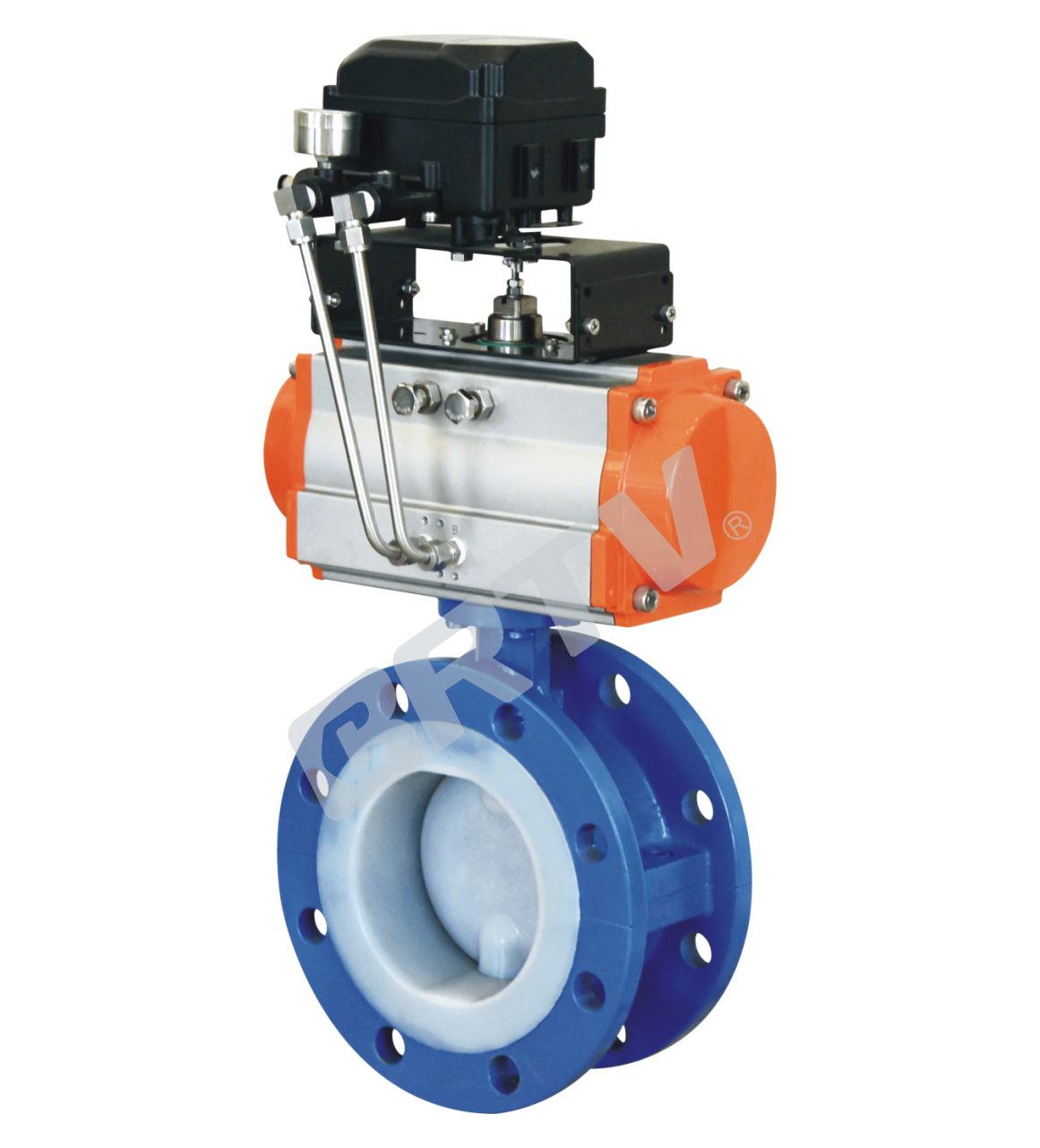
1. Flanged Fluorine Lined Butterfly Valve
Technique Standard
| Design and Manufacture | GB/T 12221 (Center Line-type); GB/T 12221 (Short Series) |
|---|
| Structure Length | ASME B16.10; JIS B2002 |
| Dimensions | GB/T9113.1; ANSI B16.5; JIS B2212 |
| Connection Size | Flange, Wafer |
| Type of Drive | Manual, Electric, Pneumatic |
| Nominal Pressure | 0.6, 1.0, 1.6, 2.5 MPa; Class150; JIS10K |
| Pressure Test | GB/T13927-92; API 598 |
Basic Model
| Manual | Worm Gearing | Pneumatic | Electric |
|---|
| D41f4/p (half lining) | D341f4/p (half lining) | D641f4/p (half lining) | D941f4/p (half lining) |
| D41f46/p (half lining) | D341f46/p (half lining) | D641f46/p (half lining) | D941f46/p (half lining) |
| D41f4 (lining) | D341f4 (lining) | D641f4 (lining) | D941f4 (lining) |
| D41f46 (lining) | D341f46 (lining) | D641f46 (lining) | D941f46 (lining) |
Form of Main Parts Materials
| Components | QT | C | P | R | PL | RL |
|---|
| Upper and lower bodies | QT400 | WCB | CF8 | CF8M | CF3 | CF3M |
| Disc | WCB | WCB | CF8 | CF8M | CF3 | CF3M |
| Shaft | 1Cr13, 40Cr | 2Cr13, 40Cr | 1Cr18Ni9Ti, 40Cr | 1Cr18Ni12Ti, 40Cr | 00Cr18Ni10, 40Cr | 00Cr17Ni14Mo2, 40Cr |
| Lining / Seat | PTFE (F4), FEP (F46), PFA, PO | | | | | |
| O-rings | FEP + FPM | | | | | |
| Elastic strip (pad) | SiR | | | | | |
| Adjustable positioning seat | 0Cr18Ni9 | 0Cr18Ni9 | 1Cr18Ni9Ti | 1Cr18Ni12Mo2Ti | 00Cr18Ni10 | 00Cr18Ni14Mo2 |
| Bolt | 35 | | 1Cr17Ni2 | 1Cr17Ni2 | 1Cr18Ni9Ti | 1Cr18Ni9Ti |
| Nut | 45 | | 0Cr19Ni9 | 0Cr18Ni9 | 0Cr18Ni9 | 0Cr18Ni9 |
| Handle | | | | A3, Z | | |
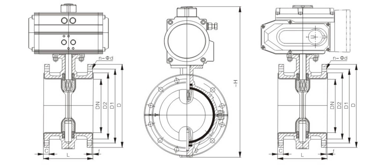
Main Outline and Connecting Flange Size
ZTD641F(F4/F46)-PN10(1.0MPa)
| DN | L | D | D1 | D2 | C | f | n-Φd | ~H | Pneumatic Actuator Model | Electric Actuator Models |
|---|
| 50 | 108 | 165 | 125 | 100 | 16 | 3 | 4-Φ18 | 190 | AT063DR/AT063SC | ZT-05 |
| 65 | 112 | 185 | 145 | 120 | 18 | 3 | 4-Φ18 | 200 | AT063DR/AT075SC | ZT-10 |
| 80 | 114 | 200 | 160 | 135 | 18 | 3 | 4(8)-Φ18 | 220 | AT075DR/AT083SC | ZT-10 |
| 100 | 127 | 220 | 180 | 155 | 20 | 3 | 8-Φ18 | 240 | AT083DR/AT092SC | ZT-15 |
| 125 | 140 | 250 | 210 | 185 | 22 | 3 | 8-Φ18 | 250 | AT105DR/AT125SC | ZT-50 |
| 150 | 140 | 285 | 240 | 210 | 22 | 3 | 8-Φ22 | 270 | AT125DR/AT140SC | ZT-50 |
| 200 | 152 | 340 | 295 | 265 | 22 | 3 | 8-Φ22 | 300 | AT140DR/AT160SC | ZT-100 |
| 250 | 165 | 395 | 350 | 320 | 24 | 3.5 | 12-Φ22 | 340 | AT160DR/AT190SC | ZT-100 |
| 300 | 178 | 445 | 400 | 368 | 26 | 3.5 | 12-Φ22 | 390 | AT190DR/AT210SC | ZT-200 |
| 350 | 190 | 505 | 460 | 428 | 26 | 4 | 16-Φ22 | 430 | AT210DR/AT240SC | ZMQ-300 |
| 400 | 216 | 565 | 515 | 482 | 26 | 4 | 16-Φ26 | 460 | AT240DR/AT270SC | ZMQ-300 |
| 450 | 222 | 615 | 565 | 532 | 26 | 4 | 20-Φ26 | 500 | AT270DR/AT350SC | ZMQ-400 |
| 500 | 229 | 670 | 620 | 585 | 28 | 5 | 20-Φ26 | 530 | AT300DR/AW28S | ZMQ-500 |
| 600 | 267 | 780 | 725 | 685 | 28 | 5 | 20-Φ30 | 700 | AT350DR/AW28S | ZDQ-800 |
| 700 | 292 | 895 | 840 | 800 | 30 | 5 | 24-Φ30 | 740 | AT400DR/AW35S | ZDQ-800 |
| 800 | 318 | 1015 | 950 | 905 | 32 | 5 | 24-Φ33 | 790 | AW28/AW40S | ZDQ-1000 |
| 900 | 330 | 1115 | 1050 | 1005 | 34 | 5 | 28-Φ33 | 850 | AW30/AW50S | ZDQ-1600 |
| 1000 | 410 | 1230 | 1160 | 1115 | 34 | 5 | 28-Φ36 | 950 | AW40/AW60S | ZDQ-2000 |
| 1200 | 470 | 1455 | 1380 | 1325 | 38 | 5 | 32-Φ39 | 1110 | AW50 | ZDQ-2500 |
ZTD641F(F4/F46)-PN16(1.6MPa)
| DN | L | D | D1 | D2 | C | f | n-Φd | ~H | Pneumatic Actuator Model | Electric Actuator Models |
|---|
| 50 | 108 | 165 | 125 | 100 | 16 | 3 | 4-Φ18 | 190 | AT075DR/AT083SC | ZT-10 |
| 65 | 112 | 185 | 145 | 120 | 18 | 3 | 4(8)-Φ18 | 200 | AT083DR/AT092SC | ZT-15 |
| 80 | 114 | 200 | 160 | 135 | 20 | 3 | 8-Φ18 | 220 | AT105DR/AT125SC | ZT-50 |
| 100 | 127 | 220 | 180 | 155 | 20 | 3 | 8-Φ18 | 240 | AT125DR/AT140SC | ZT-50 |
| 125 | 140 | 250 | 210 | 185 | 22 | 3 | 8-Φ18 | 250 | AT140DR/AT160SC | ZT-100 |
| 150 | 140 | 285 | 240 | 210 | 22 | 3 | 8-Φ22 | 270 | AT160DR/AT190SC | ZT-100 |
| 200 | 152 | 340 | 295 | 265 | 24 | 3 | 12-Φ22 | 310 | AT190DR/AT210SC | ZT-200 |
| 250 | 165 | 405 | 355 | 320 | 26 | 3.5 | 12-Φ26 | 340 | AT210DR/AT240SC | ZMQ-300 |
| 300 | 178 | 460 | 410 | 375 | 28 | 3.5 | 12-Φ26 | 390 | AT240DR/AT270SC | ZMQ-300 |
| 350 | 190 | 520 | 470 | 435 | 32 | 4 | 16-Φ26 | 430 | AT270DR/AT350SC | ZMQ-400 |
| 400 | 216 | 580 | 525 | 485 | 36 | 4 | 16-Φ30 | 460 | AT300DR/AW28S | ZMQ-500 |
| 450 | 222 | 640 | 585 | 545 | 38 | 4 | 20-Φ30 | 500 | AT350DR/AW28S | ZDQ-800 |
| 500 | 229 | 715 | 650 | 608 | 42 | 5 | 20-Φ33 | 530 | AT400DR/AW35S | ZDQ-800 |
| 600 | 267 | 840 | 770 | 718 | 46 | 5 | 20-Φ36 | 700 | AW28/AW40S | ZDQ-1000 |
| 700 | 292 | 910 | 840 | 788 | 48 | 5 | 24-Φ36 | 740 | AW30/AW50S | ZDQ-1600 |
| 800 | 318 | 1025 | 950 | 898 | 50 | 5 | 24-Φ39 | 790 | AW40/AW60S | ZDQ-2000 |
| 900 | 330 | 1125 | 1050 | 998 | 52 | 5 | 28-Φ39 | 850 | AW50 | ZDQ-2500 |
| 1000 | 410 | 1255 | 1170 | 1110 | 54 | 5 | 28-Φ42 | 950 | AW60 | ZDQ-3000 |
Fluorine Lined Butterfly Valve Series
(1).The basic types include ZTD671F4 and ZTD671F46 (center-line) fully lined wafer-type butterfly valves. The valve body adopts a two-piece split structure, and the valve seat is integrally lined with the valve body. During operation, only the fully lined plastic seat and the butterfly disc come into contact with the medium. The valve can withstand corrosion from almost all media (except molten metal and elemental fluorine).
In the D71F46 type, the valve stem and butterfly disc (forged) are integrated as one piece, and the surface is fully coated with FEP. The inner surface of the valve body flow channel is smooth, resulting in low fluid resistance, high Cv value, strong flow capacity, and moderate operating torque. A four-stage sealing structure is adopted, and a temperature-resistant and aging-resistant silicone rubber elastic seat is arranged outside the sealing surface, achieving zero leakage of the medium.
(2).Based on the above models, the ZTD641F4 and ZTD641F46 flange-connection butterfly valves are developed. The valve body is fully lined, while the butterfly disc is made of stainless steel with a semi-lined structure.
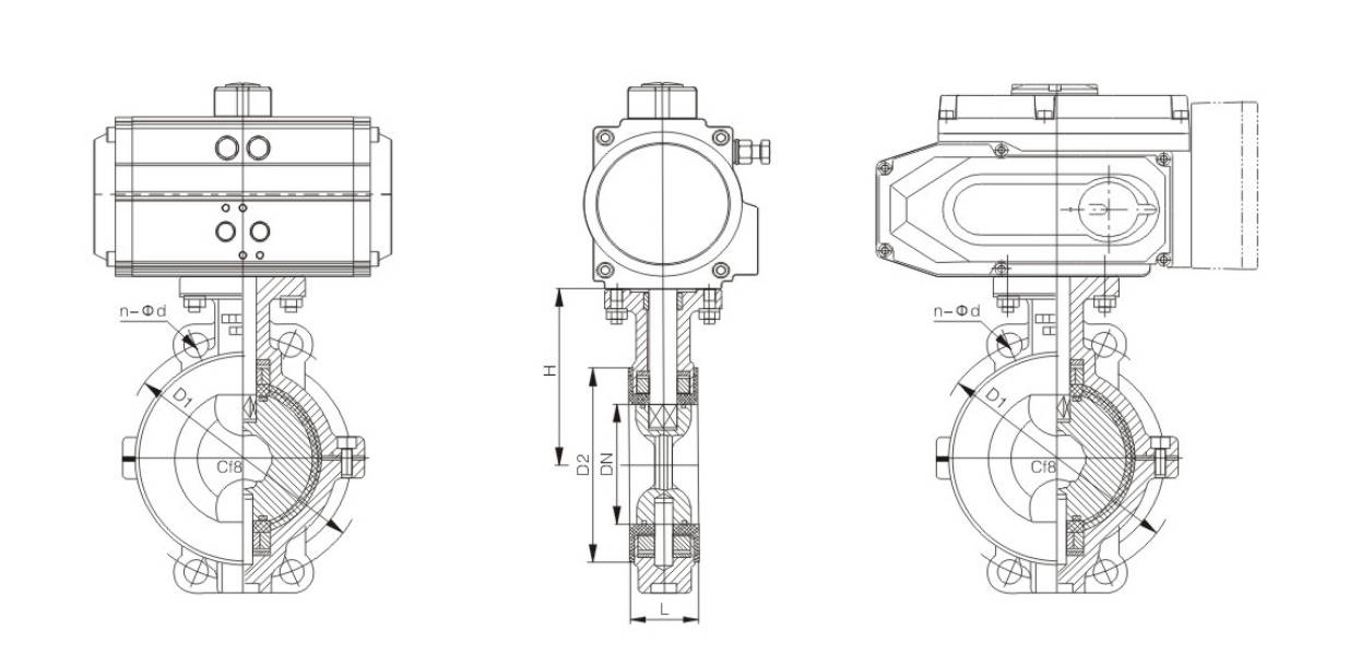
Structural Features
(1).The center-line butterfly valve design ensures that the butterfly disc and seat are concentric (centered) within a 360° circumference, providing bi-directional sealing performance. Pressure and flow rate can be adjusted freely.
(2).A four-stage loaded elastic sealing structure ensures absolute zero leakage both internally and externally:
A. A specially designed transition curve between the shaft head and the circumference of the butterfly disc ensures smooth transition with the valve seat.
B. The shaft end face adopts a combination of elastic O-ring, rigid steel washer at the shaft shoulder, and elastic rubber gasket.
C. The radial sealing of the shaft adopts a combination of O-ring and metal gasket.
D. The valve seat is embedded in the elastic groove of the valve body.
(3).An adjustable elastic pin positioning structure is adopted, ensuring accurate positioning and a simple structure.
Basic Model
| Operation Type | Model Variants |
|---|
| Manually | D41F/P (semi lined), D41F₃ (fully lined), D41F₄₆ (fully lined) |
| Pneumatic | D641F/P (semi lined), D641F₃ (fully lined), D641F₄₆ (fully lined) |
| Worm wheel operated | D341F/P (semi lined), D341F₃ (fully lined), D341F₄₆ (fully lined) |
| Electric | D941F/P (semi lined), D941F₃ (fully lined), D941F₄₆ (fully lined) |
Executive Standard
| Design and manufacture | GB 12238 (Middle line) |
|---|
| Face to face | GB 12221 (Short-long pattern) |
| Flange dimension | JB78 / JB79 (or according to contract) |
| Pressure test | GB/T 13927 |
| Symbol | GB 12220 |
| Supply | GB/T 12252 |
Main Parts Material Specifications
| No. | Parts name | Grey cast iron (Z) | Carbon steel (C) | Stainless steel (P) | Stainless steel (R) | Low carbon SS (PL) | Low carbon SS (RL) |
|---|
| 1 | Body | HT250 | WCB | CF8 | CF8M | CF3 | CF3M |
| 2 | Stem / Pin | 1Cr13 | 2Cr13 | 1Cr18Ni9Ti | 1Cr18Ni12Mo2Ti | 00Cr18Ni10 | 00Cr17Ni14Mo2 |
| 3 | Lining / Seat | — | PTFE / PCTFE / FEP / PFA | — | — | PO | — |
| 4 | Disc / Packing gland | WCB | WCB | CF8 | CF8M | CF3 | CF3M |
| 5 | Yoke | WCB (cast steel) | WCB | CF8 | CF8M | CF3 | CF3M |
| 6 | Packing | PTFE | PTFE | PTFE | PTFE | PTFE | PTFE |
| 7 | Bolt | 35 | 35 | 1Cr17Ni2 | 1Cr17Ni2 | 1Cr18Ni9Ti | 1Cr18Ni9Ti |
| 8 | Nut | 45 | 45 | 0Cr18Ni9 | 0Cr18Ni9 | 0Cr18Ni9 | 0Cr18Ni9 |
Main Dimension
PN0.6 MPa
| DN (mm) | NPS (inch) | L | D | D1 | D2 | f | b | Z-Φd | DO | H | W (kg) |
|---|
| 40 | 1 1/2 | 106 | 130 | 100 | 80 | 3 | 16 | 4-Φ14 | 160 | 140 | 10 |
| 50 | 2 | 108 | 140 | 110 | 90 | 3 | 16 | 4-Φ14 | 200 | 160 | 12 |
| 65 | 2 1/2 | 112 | 160 | 130 | 110 | 3 | 16 | 4-Φ14 | 250 | 160 | 13 |
| 80 | 3 | 114 | 185 | 150 | 125 | 3 | 18 | 4-Φ18 | 250 | 170 | 14 |
| 100 | 4 | 127 | 205 | 170 | 145 | 3 | 18 | 4-Φ18 | 300 | 180 | 16 |
| 125 | 5 | 140 | 235 | 200 | 175 | 3 | 20 | 8-Φ18 | 300 | 275 | 18 |
| 150 | 6 | 140 | 260 | 225 | 200 | 3 | 20 | 8-Φ18 | 200* | 295 | 38 |
| 200 | 8 | 152 | 315 | 280 | 255 | 3 | 22 | 8-Φ18 | 200* | 320 | 74 |
| 250 | 10 | 250 | 370 | 335 | 310 | 3 | 24 | 12-Φ18 | 240* | 385 | 105 |
| 300 | 12 | 270 | 435 | 395 | 362 | 4 | 24 | 12-Φ23 | 240* | 390 | 142 |
| 350 | 14 | 290 | 485 | 445 | 412 | 4 | 26 | 12-Φ23 | 240* | 460 | 179 |
| 400 | 16 | 310 | 535 | 495 | 462 | 4 | 28 | 16-Φ23 | 280* | 510 | 220 |
| 450 | 18 | 330 | 590 | 550 | 518 | 4 | 28 | 16-Φ23 | 280* | 540 | 268 |
| 500 | 20 | 350 | 640 | 600 | 568 | 4 | 30 | 16-Φ23 | 320* | 570 | 378 |
| 600 | 24 | 390 | 755 | 705 | 670 | 5 | 30 | 20-Φ25 | 320* | 660 | 608 |
| 700 | 28 | 430 | 860 | 810 | 775 | 5 | 32 | 24-Φ25 | 360* | 710 | 1050 |
| 800 | 32 | 470 | 975 | 920 | 880 | 5 | 34 | 24-Φ30 | 360* | 780 | 1320 |
| 900 | 36 | 510 | 1075 | 1020 | 980 | 5 | 36 | 24-Φ30 | 380* | 885 | 1795 |
| 1000 | 40 | 550 | 1175 | 1120 | 1080 | 5 | 36 | 28-Φ30 | 400* | 990 | 1900 |
| 1200 | 48 | 630 | 1400 | 1340 | 1295 | 5 | 40 | 32-Φ34 | 400* | 1170 | 2110 |
PN1.0 MPa
| DN (mm) | NPS (inch) | L | D | D1 | D2 | f | b | Z-Φd | DO | H | W (kg) |
|---|
| 40 | 1 1/2 | 106 | 145 | 110 | 85 | 3 | 18 | 4-Φ18 | 160 | 140 | 10 |
| 50 | 2 | 108 | 160 | 125 | 100 | 3 | 20 | 4-Φ18 | 200 | 160 | 12 |
| 65 | 2 1/2 | 112 | 180 | 145 | 120 | 3 | 20 | 4-Φ18 | 250 | 165 | 13 |
| 80 | 3 | 114 | 195 | 160 | 135 | 3 | 22 | 4-Φ18 | 250 | 170 | 14 |
| 100 | 4 | 127 | 215 | 180 | 155 | 3 | 22 | 8-Φ18 | 300 | 180 | 16 |
| 125 | 5 | 140 | 245 | 210 | 185 | 3 | 24 | 8-Φ18 | 300 | 275 | 18 |
| 150 | 6 | 140 | 280 | 240 | 210 | 3 | 24 | 8-Φ23 | 200* | 295 | 38 |
| 200 | 8 | 152 | 335 | 295 | 265 | 3 | 26 | 8-Φ23 | 200* | 320 | 74 |
| 250 | 10 | 250 | 390 | 350 | 320 | 3 | 28 | 12-Φ23 | 240* | 385 | 105 |
| 300 | 12 | 270 | 440 | 400 | 368 | 4 | 28 | 12-Φ23 | 240* | 390 | 142 |
| 350 | 14 | 290 | 500 | 460 | 428 | 4 | 30 | 16-Φ23 | 240* | 460 | 179 |
| 400 | 16 | 310 | 565 | 515 | 482 | 4 | 32 | 16-Φ25 | 280* | 510 | 220 |
| 450 | 18 | 330 | 615 | 565 | 532 | 4 | 32 | 20-Φ25 | 280* | 540 | 268 |
| 500 | 20 | 350 | 670 | 620 | 585 | 4 | 34 | 20-Φ25 | 320* | 570 | 378 |
| 600 | 24 | 390 | 780 | 725 | 685 | 5 | 36 | 20-Φ30 | 320* | 660 | 608 |
| 700 | 28 | 430 | 895 | 840 | 800 | 5 | 40 | 24-Φ30 | 360* | 710 | 1050 |
| 800 | 32 | 470 | 1010 | 950 | 905 | 5 | 44 | 24-Φ34 | 360* | 780 | 1320 |
| 900 | 36 | 510 | 1110 | 1050 | 1005 | 5 | 46 | 28-Φ34 | 380* | 885 | 1795 |
| 1000 | 40 | 550 | 1220 | 1160 | 1115 | 5 | 50 | 28-Φ34 | 400* | 990 | 1900 |
PN1.6 MPa
| DN (mm) | NPS (inch) | L | D | D1 | D2 | f | b | Z-Φd | DO | H | W (kg) |
|---|
| 40 | 1 1/2 | 106 | 145 | 110 | 85 | 3 | 18 | 4-Φ18 | 160 | 140 | 10 |
| 50 | 2 | 108 | 160 | 125 | 100 | 3 | 20 | 4-Φ18 | 200 | 160 | 12 |
| 65 | 2 1/2 | 112 | 180 | 145 | 120 | 3 | 20 | 4-Φ18 | 250 | 165 | 13 |
| 80 | 3 | 114 | 195 | 160 | 135 | 3 | 22 | 8-Φ18 | 260 | 170 | 14 |
| 100 | 4 | 127 | 215 | 180 | 155 | 3 | 24 | 8-Φ18 | 300 | 180 | 16 |
| 125 | 5 | 140 | 245 | 210 | 185 | 3 | 26 | 8-Φ18 | 300 | 275 | 18 |
| 150 | 6 | 140 | 280 | 240 | 210 | 3 | 28 | 8-Φ23 | 200* | 295 | 42 |
| 200 | 8 | 152 | 335 | 295 | 265 | 3 | 30 | 12-Φ23 | 200* | 320 | 78 |
| 250 | 10 | 250 | 405 | 355 | 320 | 3 | 32 | 12-Φ25 | 240* | 385 | 120 |
| 300 | 12 | 270 | 460 | 410 | 375 | 4 | 34 | 12-Φ25 | 240* | 390 | 145 |
| 350 | 14 | 290 | 520 | 470 | 435 | 4 | 38 | 16-Φ25 | 240* | 460 | 202 |
| 400 | 16 | 310 | 580 | 525 | 485 | 4 | 40 | 16-Φ30 | 280* | 510 | 235 |
| 450 | 18 | 330 | 640 | 585 | 545 | 4 | 44 | 20-Φ30 | 280* | 540 | 368 |
| 500 | 20 | 350 | 705 | 650 | 608 | 4 | 46 | 20-Φ34 | 320* | 570 | 420 |
| 600 | 24 | 390 | 840 | 770 | 718 | 5 | 54 | 20-Φ41 | 320* | 660 | 750 |
| 700 | 28 | 430 | 910 | 840 | 788 | 5 | 54 | 24-Φ41 | 360* | 710 | 1028 |
| 800 | 32 | 470 | 1020 | 950 | 898 | 5 | 54 | 24-Φ41 | 380* | 780 | 1690 |
| 900 | 36 | 510 | 1120 | 1050 | 998 | 5 | 54 | 28-Φ41 | 400* | 885 | 1815 |
| 1000 | 40 | 550 | 1255 | 1170 | 1110 | 5 | 60 | 28-Φ48 | 500* | 990 | 2050 |
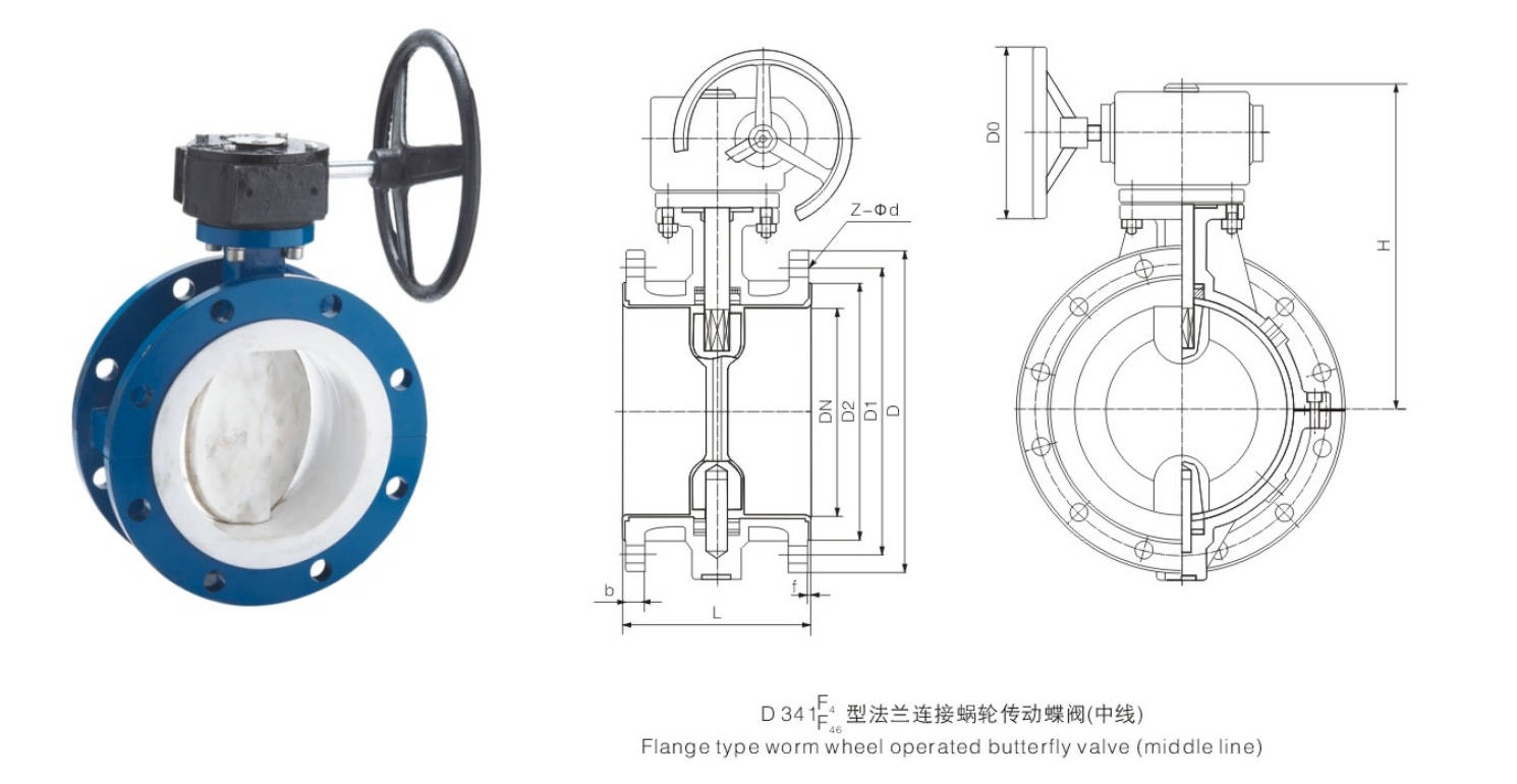
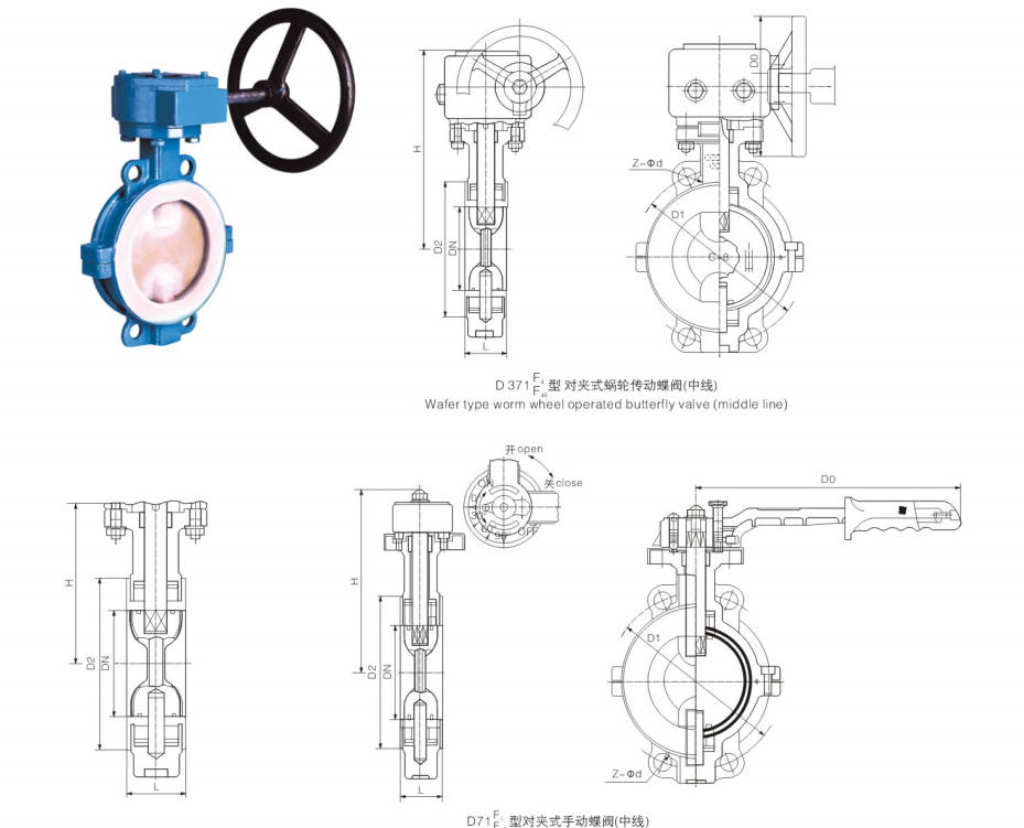
2. Wafer Fluorine Lined Butterfly Valve
The wafer Butterfly Valves (center line-type):
Design and manufacture in accordance with the basic form of China's national standards, which means that disc shaft coincident with body or seat center.
Butterfly valve is with the stem together with the rotation of the butterfly plate as the opening and closing parts, to achieve the valve open, close and adjust.
Butterfly valve is a kind of valve to open, close, and adjust by on–off switch. And the on–off switch is composed with the stem and rotating disc.
Except from truncation and interception in the pipeline, butterfly valve has been the sealing performance in recent years. In addition, the butterfly valve has the advantages of small volume, light weight, simple structure, etc.
Compared with the same parameters gate valve, when the flat height is up to 30–50%, the butterfly plate can rotate 90° and can open or close valve. The force is approximately equal, the torque is opposite, so the opening and closing force distance is small.
a. ZTD671F46 – The lining type, which means lining body, lining butterfly plate, butterfly plate and butterfly plate shaft are integrated.
b. ZTD671F4 – The lining type, which means lining body, lining butterfly plate, butterfly plate and butterfly plate shaft are assembled.
c. ZTD671F/P – The half lining type, which means lining body, stainless steel of butterfly plate (not lined), butterfly plate and butterfly plate are assembled.
Technique Standard
| Design and Manufacture | GB/T 12238 (Center Line-type) |
|---|
| Structure Length | GB/T 12221 (Short series) |
| Flange Dimensions | GB/T 9113, JB/T 79.1 |
| Pressure Test | GB/T 13927 |
| Mark | GB/T 12220 |
| Supply | GB/T 12252 |
| Manual | Worm Gearing | Pneumatic | Electric |
|---|
| D71F/P (half lining) | D371F/P (half lining) | D671F/P (half lining) | D971F/P (half lining) |
| D71F3 (lining) | D371F3 (lining) | D671F3 (lining) | D971F3 (lining) |
| D71F4 (lining) | D371F4 (lining) | D671F4 (lining) | D971F4 (lining) |
| D71F46 (lining) | D371F46 (lining) | D671F46 (lining) | D971F46 (lining) |
Reference Table of Butterfly Valve Driving Torque
| Nominal Diameter (mm) | Inch | 0.6–1.0 MPa (N·m) | 1.6 MPa Class150 (N·m) |
|---|
| 40 | 1 1/2 | 37 | 50 |
| 50 | 2 | 45 | 90 |
| 65 | 2 1/2 | 75 | 120 |
| 80 | 3 | 110 | 160 |
| 100 | 4 | 140 | 200 |
| 125 | 5 | 190 | 250 |
| 150 | 6 | 250 | 350 |
| 200 | 8 | 360 | 500 |
| 250 | 10 | 530 | 750 |
| 300 | 12 | 800 | 1000 |
| 350 | 14 | 1150 | 1500 |
| 400 | 16 | 1500 | 1900 |
| 450 | 18 | 2200 | 2500 |
| 500 | 20 | 3000 | 3500 |
| 600 | 24 | 4500 | 6000 |
| 700 | 28 | 6500 | |
| 800 | 32 | 9000 | |
| 900 | 36 | 14000 | |
| 1000 | 40 | 22500 | |
| 1200 | 48 | 30000 | |
Form of Main Parts Materials
| Components | Z (Gray Cast Iron) | C (Carbon Steel) | P (Stainless Steel) | R (Stainless Steel) | PL (Ultra-low Carbon Stainless Steel) | RL (Ultra-low Carbon Stainless Steel) |
|---|
| Upper and Lower Bodies | HT250 | WCB | CF8 | CF8M | CF3 | CF3M |
| Disc | WCB | 35 (forging) | CF8 | CF8M | CF3 | CF3M |
| Butterfly Disc Shaft | 1Cr13 | 2Cr13 | 1Cr18Ni9Ti | 1Cr18Ni12Mo2Ti | 00Cr18Ni10 | 00Cr18Ni14Mo2 |
| Lining / Seat | PTFE (F4), PCTFE (F3), FEP (F46), PFA, PO | | | | | |
| O-rings | FPM | | | | | |
| Elastic Strip (Pad) | SiR | | | | | |
| Adjustable Positioning Seat | 0Cr18Ni9 | 0Cr18Ni9 | 1Cr18Ni9Ti | 1Cr18Ni12Mo2Ti | 00Cr18Ni10 | 00Cr18Ni14Mo2 |
| Bolt | 35 | 35 | 1Cr17Ni2 | 1Cr17Ni2 | 1Cr18Ni9Ti | 1Cr18Ni9Ti |
| Nut | 45 | 45 | 0Cr18Ni9 | 0Cr18Ni9 | 0Cr18Ni9 | 0Cr18Ni9 |
| Handle | ZL101 (cast iron aluminum alloy) | | | | | |
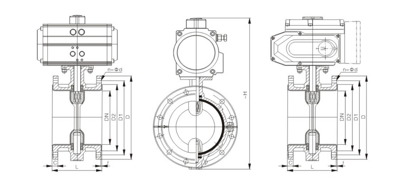
Main Outline and Connecting Flange Size
ZTD671F(F4/F46)-PN6(0.6MPa)
| DN | inch | L | D | D1 | D2 | n-Φd | H | Pneumatic Actuator Model | Electric Actuator Models |
|---|
| 40 | 1 1/2 | 33 | 130 | 100 | 80 | 4-Φ14 | 140 | AT063DR/AT063SC | ZT-05 |
| 50 | 2 | 43 | 140 | 110 | 90 | 4-Φ14 | 145 | AT063DR/AT075SC | ZT-10 |
| 65 | 2 1/2 | 46 | 160 | 130 | 110 | 4-Φ14 | 155 | AT075DR/AT083SC | ZT-10 |
| 80 | 3 | 46 | 185 | 150 | 125 | 4-Φ18 | 165 | AT083DR/AT092SC | ZT-15 |
| 100 | 4 | 52 | 205 | 170 | 145 | 4-Φ18 | 180 | AT105DR/AT125SC | ZT-50 |
| 125 | 5 | 56 | 235 | 200 | 175 | 8-Φ18 | 203 | AT125DR/AT140SC | ZT-50 |
| 150 | 6 | 56 | 260 | 225 | 200 | 8-Φ18 | 225 | AT140DR/AT160SC | ZT-100 |
| 200 | 8 | 60 | 315 | 280 | 255 | 8-Φ18 | 275 | AT160DR/AT190SC | ZT-100 |
| 250 | 10 | 68 | 370 | 335 | 310 | 12-Φ18 | 315 | AT190DR/AT210SC | ZT-200 |
| 300 | 12 | 78 | 435 | 395 | 362 | 12-Φ23 | 348 | AT210DR/AT240SC | ZMQ-300 |
| 350 | 14 | 78 | 485 | 445 | 412 | 12-Φ23 | 415 | AT240DR/AT270SC | ZMQ-300 |
| 400 | 16 | 102 | 535 | 495 | 462 | 16-Φ23 | 460 | AT270DR/AT350SC | ZMQ-400 |
| 450 | 18 | 114 | 590 | 550 | 518 | 16-Φ23 | 500 | AT300DR/AW28S | ZMQ-500 |
| 500 | 20 | 127 | 640 | 600 | 568 | 16-Φ23 | 530 | AT350DR/AW28S | ZDQ-800 |
| 600 | 24 | 154 | 755 | 705 | 670 | 20-Φ25 | 610 | AT400DR/AW35S | ZDQ-800 |
| 700 | 28 | 165 | 860 | 810 | 775 | 24-Φ25 | 675 | AW28/AW40S | ZDQ-1000 |
| 800 | 32 | 190 | 975 | 920 | 880 | 24-Φ30 | 805 | AW30/AW50S | ZDQ-1600 |
| 900 | 36 | 203 | 1075 | 1020 | 980 | 24-Φ30 | 995 | AW40/AW60S | ZDQ-2000 |
| 1000 | 40 | 216 | 1175 | 1120 | 1080 | 28-Φ30 | 1170 | AW50 | ZDQ-2500 |
| 1200 | 48 | 254 | 1400 | 1340 | 1295 | 32-Φ34 | 1295 | AW60 | ZDQ-3000 |
ZTD671F(F4/F46)-PN10(1.0MPa)
| DN | inch | L | D | D1 | D2 | f | b | n-Φd | H | Pneumatic Actuator Model | Electric Actuator Models |
|---|
| 40 | 1 1/2 | 33 | 145 | 110 | 85 | 3 | 18 | 4-Φ18 | 140 | AT063DR/AT063SC | ZT-05 |
| 50 | 2 | 43 | 160 | 125 | 100 | 3 | 20 | 4-Φ18 | 145 | AT063DR/AT075SC | ZT-10 |
| 65 | 2 1/2 | 46 | 180 | 145 | 120 | 3 | 20 | 4-Φ18 | 155 | AT075DR/AT083SC | ZT-10 |
| 80 | 3 | 46 | 195 | 160 | 135 | 3 | 22 | 8-Φ18 | 165 | AT083DR/AT092SC | ZT-15 |
| 100 | 4 | 52 | 215 | 180 | 155 | 3 | 22 | 8-Φ18 | 180 | AT105DR/AT125SC | ZT-50 |
| 125 | 5 | 56 | 245 | 210 | 185 | 3 | 24 | 8-Φ18 | 203 | AT125DR/AT140SC | ZT-50 |
| 150 | 6 | 56 | 280 | 240 | 210 | 3 | 24 | 8-Φ23 | 225 | AT140DR/AT160SC | ZT-100 |
| 200 | 8 | 60 | 335 | 295 | 265 | 3 | 26 | 8-Φ23 | 275 | AT160DR/AT190SC | ZT-100 |
| 250 | 10 | 68 | 390 | 350 | 320 | 3 | 28 | 12-Φ23 | 315 | AT190DR/AT210SC | ZT-200 |
| 300 | 12 | 78 | 440 | 400 | 368 | 4 | 28 | 12-Φ23 | 348 | AT210DR/AT240SC | ZMQ-300 |
| 350 | 14 | 78 | 500 | 460 | 428 | 4 | 30 | 12-Φ23 | 415 | AT240DR/AT270SC | ZMQ-300 |
| 400 | 16 | 102 | 565 | 515 | 482 | 4 | 32 | 16-Φ23 | 460 | AT270DR/AT350SC | ZMQ-400 |
| 450 | 18 | 114 | 615 | 565 | 532 | 4 | 32 | 16-Φ25 | 500 | AT300DR/AW28S | ZMQ-500 |
| 500 | 20 | 127 | 670 | 620 | 585 | 4 | 34 | 20-Φ25 | 530 | AT350DR/AW28S | ZDQ-800 |
| 600 | 24 | 154 | 780 | 725 | 685 | 5 | 36 | 20-Φ25 | 610 | AT400DR/AW35S | ZDQ-800 |
| 700 | 28 | 165 | 895 | 840 | 800 | 5 | 40 | 20-Φ30 | 675 | AW28/AW40S | ZDQ-1000 |
| 800 | 32 | 190 | 1010 | 950 | 905 | 5 | 44 | 24-Φ30 | 805 | AW30/AW50S | ZDQ-1600 |
| 900 | 36 | 203 | 1110 | 1050 | 1005 | 5 | 46 | 24-Φ34 | 995 | AW40/AW60S | ZDQ-2000 |
| 1000 | 40 | 216 | 1220 | 1160 | 1115 | 5 | 50 | 28-Φ34 | 1170 | AW50 | ZDQ-2500 |
| 1200 | 48 | 254 | 1450 | 1380 | 1325 | 5 | 56 | 32-Φ41 | 1295 | AW60 | ZDQ-3000 |
ZTD671F(F4/F46)-PN16(1.6MPa)
| DN | inch | L | D | D1 | D2 | f | b | n-Φd | H | Pneumatic Actuator Model | Electric Actuator Models |
|---|
| 40 | 1 1/2 | 33 | 145 | 110 | 85 | 3 | 18 | 4-Φ18 | 145 | AT063DR/AT075SC | ZT-10 |
| 50 | 2 | 43 | 160 | 125 | 100 | 3 | 20 | 4-Φ18 | 150 | AT075DR/AT083SC | ZT-10 |
| 65 | 2 1/2 | 46 | 180 | 145 | 120 | 3 | 20 | 4-Φ18 | 160 | AT083DR/AT092SC | ZT-15 |
| 80 | 3 | 46 | 195 | 160 | 135 | 3 | 22 | 8-Φ18 | 170 | AT105DR/AT125SC | ZT-50 |
| 100 | 4 | 52 | 215 | 180 | 155 | 3 | 24 | 8-Φ18 | 185 | AT125DR/AT140SC | ZT-50 |
| 125 | 5 | 56 | 245 | 210 | 185 | 3 | 26 | 8-Φ18 | 210 | AT140DR/AT160SC | ZT-100 |
| 150 | 6 | 56 | 280 | 240 | 210 | 3 | 28 | 8-Φ23 | 230 | AT160DR/AT190SC | ZT-100 |
| 200 | 8 | 60 | 335 | 295 | 265 | 3 | 30 | 12-Φ23 | 285 | AT190DR/AT210SC | ZT-200 |
| 250 | 10 | 68 | 405 | 355 | 320 | 3 | 32 | 12-Φ25 | 325 | AT210DR/AT240SC | ZMQ-300 |
| 300 | 12 | 78 | 460 | 410 | 375 | 4 | 34 | 12-Φ25 | 360 | AT240DR/AT270SC | ZMQ-300 |
| 350 | 14 | 78 | 520 | 470 | 435 | 4 | 38 | 16-Φ25 | 430 | AT270DR/AT350SC | ZMQ-400 |
| 400 | 16 | 102 | 580 | 525 | 485 | 4 | 40 | 16-Φ30 | 475 | AT300DR/AW28S | ZMQ-500 |
| 450 | 18 | 114 | 640 | 585 | 545 | 4 | 44 | 20-Φ30 | 525 | AT350DR/AW28S | ZDQ-800 |
| 500 | 20 | 127 | 705 | 650 | 608 | 4 | 46 | 20-Φ34 | 565 | AT400DR/AW35S | ZDQ-800 |
| 600 | 24 | 154 | 840 | 770 | 718 | 5 | 54 | 20-Φ41 | 620 | AW28/AW40S | ZDQ-1000 |
| 700 | 28 | 165 | 910 | 840 | 788 | 5 | 54 | 24-Φ41 | 686 | AW30/AW50S | ZDQ-1600 |
| 800 | 32 | 190 | 1020 | 950 | 898 | 5 | 54 | 24-Φ41 | 815 | AW40/AW60S | ZDQ-2000 |
| 900 | 36 | 203 | 1120 | 1050 | 998 | 5 | 54 | 28-Φ41 | 1010 | AW50 | ZDQ-2500 |
| 1000 | 40 | 216 | 1255 | 1170 | 1100 | 5 | 60 | 28-Φ48 | 1185 | AW60 | ZDQ-3000 |
Basic Model
| Operation Type | Model Variants |
|---|
| Lever operated | D71F/P (semi lined), D71F/S (fully lined) |
| Pneumatic | D671F/P (semi lined), D671F/S (fully lined) |
| Worm wheel operated | D371F/P (semi lined), D371F/S (fully lined) |
| Electric | D971F/P (semi lined), D971F/S (fully lined) |
Main Dimensions
PN0.6 (MPa)
| DN | NPS | L | D | D1 | D2 | f | b | Z-φd | Do | H | W (kg) |
|---|
| 50 | 2 | 43 | 140 | 110 | 90 | 3 | 16 | 4-φ14 | 200 | 145 | 3.5 |
| 65 | 2 1/2 | 46 | 160 | 130 | 110 | 3 | 16 | 4-φ14 | 250 | 155 | 4.5 |
| 80 | 3 | 46 | 185 | 150 | 125 | 3 | 18 | 4-φ18 | 250 | 165 | 6 |
| 100 | 4 | 52 | 205 | 170 | 145 | 3 | 18 | 4-φ18 | 250 | 180 | 7.5 |
| 125 | 5 | 56 | 235 | 200 | 175 | 3 | 20 | 8-φ18 | 300 | 203 | 11 |
| 150 | 6 | 56 | 260 | 225 | 200 | 3 | 20 | 8-φ18 | 300 | 225 | 16 |
| 200 | 8 | 60 | 315 | 280 | 255 | 3 | 22 | 8-φ18 | 200* | 275 | 48 |
| 250 | 10 | 68 | 370 | 335 | 310 | 3 | 24 | 12-φ18 | 200* | 315 | 60 |
| 300 | 12 | 78 | 435 | 395 | 362 | 4 | 24 | 12-φ23 | 240* | 348 | 75 |
| 350 | 14 | 78 | 485 | 445 | 412 | 4 | 26 | 12-φ23 | 240* | 415 | 82 |
| 400 | 16 | 102 | 535 | 495 | 462 | 4 | 28 | 16-φ23 | 280* | 460 | 123 |
| 450 | 18 | 114 | 590 | 550 | 518 | 4 | 28 | 16-φ23 | 280* | 500 | 150 |
| 500 | 20 | 127 | 640 | 600 | 568 | 4 | 30 | 16-φ23 | 320* | 530 | 180 |
| 600 | 24 | 154 | 755 | 705 | 670 | 5 | 30 | 20-φ25 | 320* | 610 | 225 |
| 700 | 28 | 165 | 860 | 810 | 775 | 5 | 32 | 24-φ25 | 360* | 675 | 315 |
| 800 | 32 | 190 | 975 | 920 | 880 | 5 | 34 | 24-φ30 | 360* | 805 | 385 |
PN1.0 (MPa)
| DN | NPS | L | D | D1 | D2 | f | b | Z-φd | Do | H | W (kg) |
|---|
| 50 | 2 | 43 | 160 | 125 | 100 | 3 | 20 | 4-φ18 | 200 | 145 | 4 |
| 65 | 2 1/2 | 46 | 180 | 145 | 120 | 3 | 20 | 4-φ18 | 250 | 155 | 6 |
| 80 | 3 | 46 | 195 | 160 | 135 | 3 | 22 | 4/8-φ18 | 250 | 165 | 8 |
| 100 | 4 | 52 | 215 | 180 | 155 | 3 | 22 | 8-φ18 | 250 | 180 | 12 |
| 125 | 5 | 56 | 245 | 210 | 185 | 3 | 24 | 8-φ18 | 300 | 203 | 18 |
| 150 | 6 | 56 | 280 | 240 | 210 | 3 | 24 | 8-φ23 | 200* | 225 | 28 |
| 200 | 8 | 60 | 335 | 295 | 265 | 3 | 26 | 8-φ23 | 200* | 275 | 56 |
| 250 | 10 | 68 | 390 | 350 | 320 | 3 | 28 | 12-φ23 | 240* | 315 | 72 |
| 300 | 12 | 78 | 440 | 400 | 368 | 4 | 28 | 12-φ23 | 240* | 348 | 88 |
| 350 | 14 | 78 | 500 | 460 | 428 | 4 | 30 | 16-φ23 | 240* | 415 | 120 |
| 400 | 16 | 102 | 565 | 515 | 482 | 4 | 32 | 16-φ25 | 280* | 460 | 145 |
| 450 | 18 | 114 | 615 | 565 | 532 | 4 | 32 | 20-φ25 | 280* | 500 | 165 |
| 500 | 20 | 127 | 670 | 620 | 585 | 4 | 34 | 20-φ25 | 320* | 530 | 195 |
| 600 | 24 | 154 | 780 | 720 | 685 | 5 | 36 | 20-φ30 | 320* | 610 | 268 |
| 700 | 28 | 165 | 895 | 840 | 800 | 5 | 40 | 24-φ30 | 360* | 675 | 320 |
| 800 | 32 | 190 | 1010 | 950 | 905 | 5 | 44 | 24-φ34 | 360* | 805 | 395 |
PN1.6 (MPa)
| DN | NPS | L | D | D1 | D2 | f | b | Z-φd | Do | H | W (kg) |
|---|
| 50 | 2 | 43 | 160 | 125 | 100 | 3 | 20 | 4-φ18 | 200 | 150 | 5 |
| 65 | 2 1/2 | 46 | 180 | 145 | 120 | 3 | 20 | 4-φ18 | 250 | 160 | 7 |
| 80 | 3 | 46 | 195 | 160 | 135 | 3 | 22 | 8-φ18 | 250 | 170 | 10 |
| 100 | 4 | 52 | 215 | 180 | 155 | 3 | 24 | 8-φ18 | 250 | 180 | 14 |
| 125 | 5 | 56 | 245 | 210 | 185 | 3 | 26 | 8-φ18 | 300 | 210 | 22 |
| 150 | 6 | 56 | 280 | 240 | 210 | 3 | 28 | 8-φ23 | 200* | 230 | 32 |
| 200 | 8 | 60 | 335 | 295 | 265 | 3 | 30 | 12-φ23 | 240* | 285 | 66 |
| 250 | 10 | 68 | 405 | 355 | 320 | 3 | 32 | 12-φ25 | 240* | 325 | 80 |
| 300 | 12 | 78 | 460 | 410 | 375 | 4 | 34 | 12-φ25 | 280* | 360 | 94 |
| 350 | 14 | 78 | 520 | 470 | 435 | 4 | 38 | 16-φ25 | 280* | 430 | 125 |
| 400 | 16 | 102 | 580 | 525 | 485 | 4 | 40 | 16-φ30 | 320* | 475 | 150 |
| 450 | 18 | 114 | 640 | 585 | 545 | 4 | 44 | 20-φ30 | 320* | 525 | 172 |
| 500 | 20 | 127 | 705 | 650 | 608 | 4 | 46 | 20-φ34 | 320* | 565 | 225 |
| 600 | 24 | 154 | 840 | 770 | 718 | 5 | 54 | 20-φ41 | 360* | 620 | 290 |
| 700 | 28 | 165 | 910 | 840 | 788 | 5 | 54 | 24-φ41 | 360* | 686 | 330 |
| 800 | 32 | 190 | 1020 | 950 | 898 | 5 | 54 | 24-φ41 | 380* | 815 | 425 |
Manufacturing Process
Step 1: Order and Design
According to the customer’s working conditions, such as pressure, temperature, medium, and flange standard, the design team confirms the structure, dimensions, and lining material of the fluorine lined butterfly valve. Drawings and production requirements are then prepared for manufacturing.
Step 2: Forging & Casting
The valve body, disc, and other main metal parts are produced by casting or forging based on the design requirements. For a fluorine lined butterfly valve, the body material must have enough strength and good dimensional stability to ensure reliable lining performance in later processing.
Step 3: Machining
After casting inspection, all parts are machined, including body bore, flange faces, shaft holes, and disc dimensions. Accurate machining is very important for the fluorine lined butterfly valve, because it directly affects sealing performance and lining fit.
Step 4: Assembly
After machining, the fluorine lining parts are installed or molded into the valve body and disc, and then the shaft, seat, actuator, and other components are assembled. During this step, special attention is paid to the concentricity and sealing surface of the fluorine lined butterfly valve.
Step 5: Testing & Quality Assurance
Each fluorine lined butterfly valve must undergo pressure testing, sealing testing, lining inspection, and operation testing before delivery. Quality control ensures that the valve has good corrosion resistance, zero leakage performance, and stable operation.
Step 6: Painting and Finishing
After final inspection, the external metal surface is cleaned, painted, and marked. Then the valve is packed properly to protect it during transportation and storage.
Applications
The fluorine lined butterfly valve, with its outstanding features such as excellent corrosion resistance, wear resistance, good sealing performance and adaptability to complex working conditions, has been widely applied in various industries including chemical engineering, petroleum and natural gas, power, new energy, biomedicine, information technology, food and beverage, and environmental protection. It can achieve stable, clean and efficient fluid control in complex media environments such as strong acids and alkalis, organic solvents, high-purity media, sewage and waste gas. With the upgrading of the chemical industry, the expansion of new energy, the strengthening of environmental protection governance and the development of high-end manufacturing, its market demand continues to grow and the market size shows a steadily rising trend.
These valves are widely used in:
Agriculture and Irrigation
Factory Environment
Why Choose Us
Superior Quality

Our valves are manufactured using premium materials and undergo rigorous quality testing to ensure reliable performance in demanding industrial applications.
Advanced Technology

Equipped with state-of-the-art CNC machining centers and precision manufacturing equipment, we deliver valves with exceptional accuracy and consistency.
Competitive Pricing

Through optimized manufacturing processes and bulk material procurement, we offer high-quality valves at competitive prices without compromising on quality.
Expert Support

Our experienced technical team provides comprehensive support from product selection to after-sales service, ensuring optimal valve performance for your specific application.