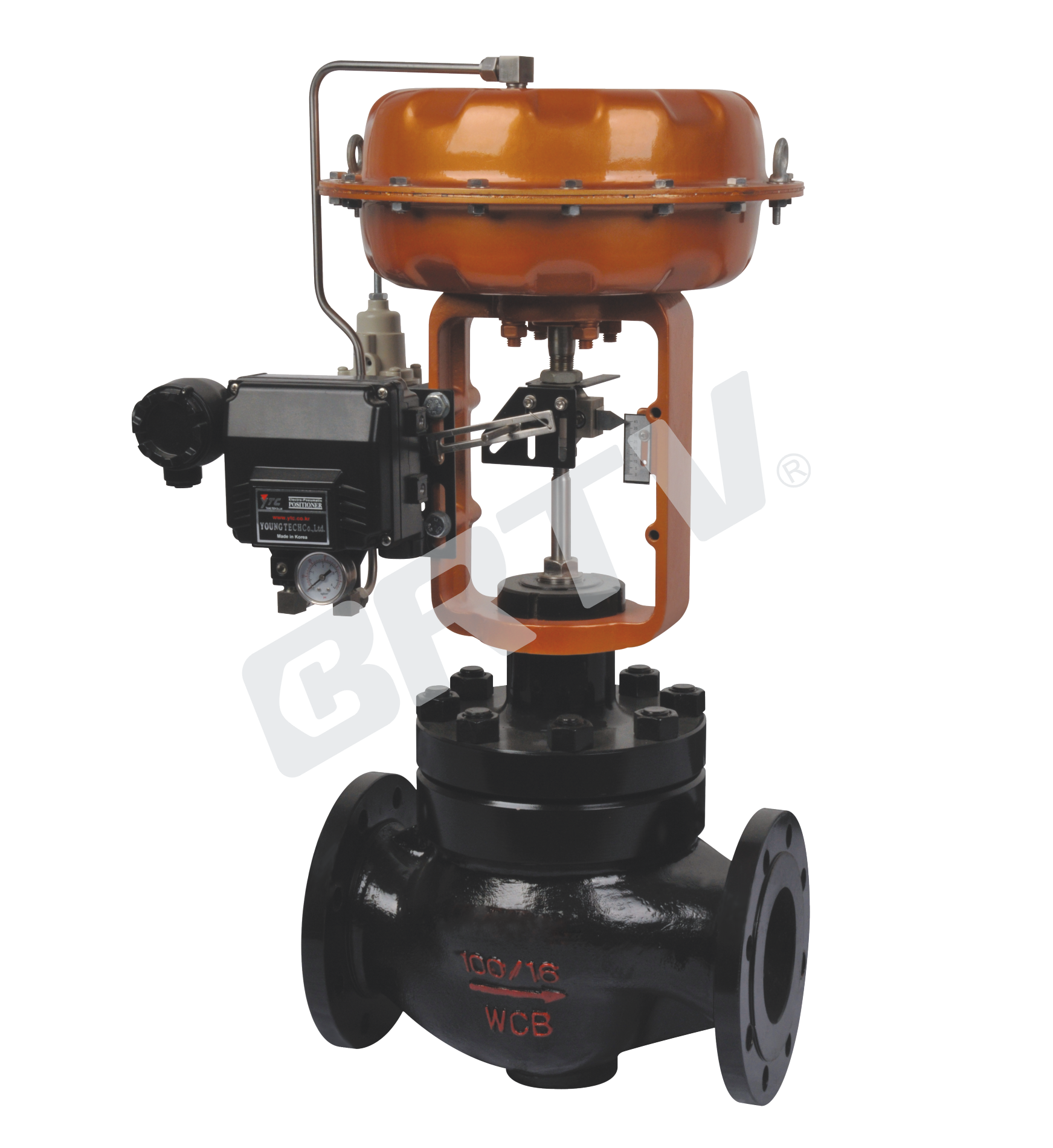
Single Seat Control Valve
Single seat control valve is a kind of control valve with top guiding structure. It has "S–streamline" fluid channel, small pressure drops, large flow and adjustable range. It has high accuracy of flow characteristic, large plug guiding area, good vibration resistance.
It is equipped with multi–spring pneumatic diaphragm actuator or electric actuator. It has characteristics of small size, light weight, large output force, easy installation, which can be used to control a variety of different pressure and temperature of the fluid.
Standard Specification
| Manner | Straight Through Single Seat Cast Ball Valve |
|---|
| Nominal Diameter | 15, 20, 25, 32, 40, 50, 65, 80, 100, 125, 150, 200 mm |
| Nominal Pressure | ANSI Class 150, 300, 600; JIS 10K, 20K, 30K, 40K; PN 1.6, 4.0, 6.4 MPa |
| Type of Connection | Flange Type: FF, RF, RJ, TG, MFM / Weld Type: SW (40–50 mm), BW (65–200 mm) |
| Body and Bonnet Material | SCPH2, WCB, SCPH21, WC6, SCS13A/CF8, SCS14A/CF8M, SCS16A/CF3M, Ti |
| Body and Bonnet Operating Range | Pressure and temperature range depend on material |
| Bonnet Manner | Normal Temperature (P): −17 ~ +230 °C / High Temperature (e): −45 ~ +230 ~ +566 °C / Extension Type (e li): −100 ~ −45 °C |
| Gland Manner | Screw Fastening Type |
| Packing | V-type PTFE Packing, Graphite Packing |
| Gasket | Zigzag |
| Surface Coating | Blue (Epoxy). When the valve body material is stainless steel, coating is not applied. |
Cv Valve and Stroke
| Nominal Diameter | 15 | 15 | 15 | 20 | 20 | 25 | 25 | 32 | 32 | 40 | 40 | 50 | 50 |
|---|
| Seat Diameter | 10 | 12 | 15 | 15 | 20 | 20 | 25 | 25 | 32 | 25 | 32 | 32 | 40 |
| Rated Cv | 1.6 | 2.5 | 4 | 4 | 6.3 | 6.3 | 10 | 10 | 17 | 10 | 17 | 24 | 17 |
| Rated Stroke | 16 | 16 | 16 | 16 | 16 | 16 | 16 | 16 | 16 | 25 | 25 | 25 | 25 |
| Nominal Diameter | 65 | 65 | 65 | 80 | 80 | 80 | 100 | 100 | 100 | 125 | 125 | 125 | 150 | 150 | 150 | 200 |
|---|
| Seat Diameter | 40 | 50 | 65 | 50 | 65 | 80 | 65 | 80 | 100 | 80 | 100 | 125 | 100 | 125 | 150 | 125 |
| Rated Cv | 24 | 40 | 63 | 40 | 63 | 100 | 63 | 100 | 160 | 100 | 160 | 250 | 160 | 250 | 400 | 250 |
| Rated Stroke | 40 | 40 | 40 | 40 | 40 | 40 | 40 | 40 | 40 | 60 | 60 | 60 | 60 | 60 | 60 | 60 |
Actuator
| Item | Pneumatic Diaphragm Type | Cylinder Piston Type | Electronic Type | Intelligent Type |
|---|
| Model | ZJHA/B | ZTCLS / ZTCL | 381 Series | ZM Series |
| Springs Type | Multiple Springs | Single Action / Double Action | — | — |
| Service | Regulation | Regulation | Regulation | Regulation |
| Supply Gas Pressure and Supply Voltage | Supply Gas Pressure (Spring Range): 140(20–100) kPa; 160(20–100) kPa; 280(80–240) kPa; 400(80–240) kPa | Supply Gas Pressure: 300–500 kPa | Voltage: 220 / 380 V 50 Hz; Input Signal: 4–20 mA DC | Voltage: 220 / 380 V 50 Hz; Input Signal: 4–20 mA DC |
| Connector | Air Piping: Rc1/4 | Air Piping: G1/8; G1/4; G1/2; G3/8 | Wiring: PG13.5 | Wiring: PG13.5 |
| Positive Action | Adding Pressure – Valve Will Be Closed | Adding Pressure – Valve Will Be Closed | Inputting the Signal – Valve Will Be Closed | Inputting the Signal – Valve Will Be Closed |
| Negative Action | Adding Pressure – Valve Will Be Opened | Adding Pressure – Valve Will Be Opened | Inputting the Signal – Valve Will Be Opened | Inputting the Signal – Valve Will Be Opened |
| Hysteresis | ≤1% FS (With Positioner); ≤3% FS (No Positioner); ≤5% FS (Match Type HA1) | ≤1% FS (With Positioner); ≤3% FS (No Positioner) | ≤±1% FS | ≤±1% FS |
| Limit of Intrinsic Error | ≤±1% FS (With Positioner); ≤±2% FS (Match Type); ≤±1% FS (No Positioner) | ≤±1% FS (With Positioner); ≤±1.5% FS (No Positioner); ≤±5% FS (Match Type) | ≤±1% FS | ≤±1% FS |
| Ambient Temperature | Standard: −30 ~ +70°C; High Temp: 0 ~ +100°C; Low Temp: −40 ~ +40°C | Standard: −20 ~ +60°C; High Temp: 0 ~ +100°C; Low Temp: −50 ~ +60°C | −20 ~ +70°C | −25 ~ +70°C |
| Painting Color | Blue Scale 10B5/10 | Blue Scale 10B5/10 | — | — |
| Accessory | Positioner / Air Filter / Pressure Reducing Valve / Transmitter / Handwheel | Positioner / Air Filter / Pressure Reducing Valve / Transmitter / Handwheel | Integrated Type | Integrated Type |
Remark:
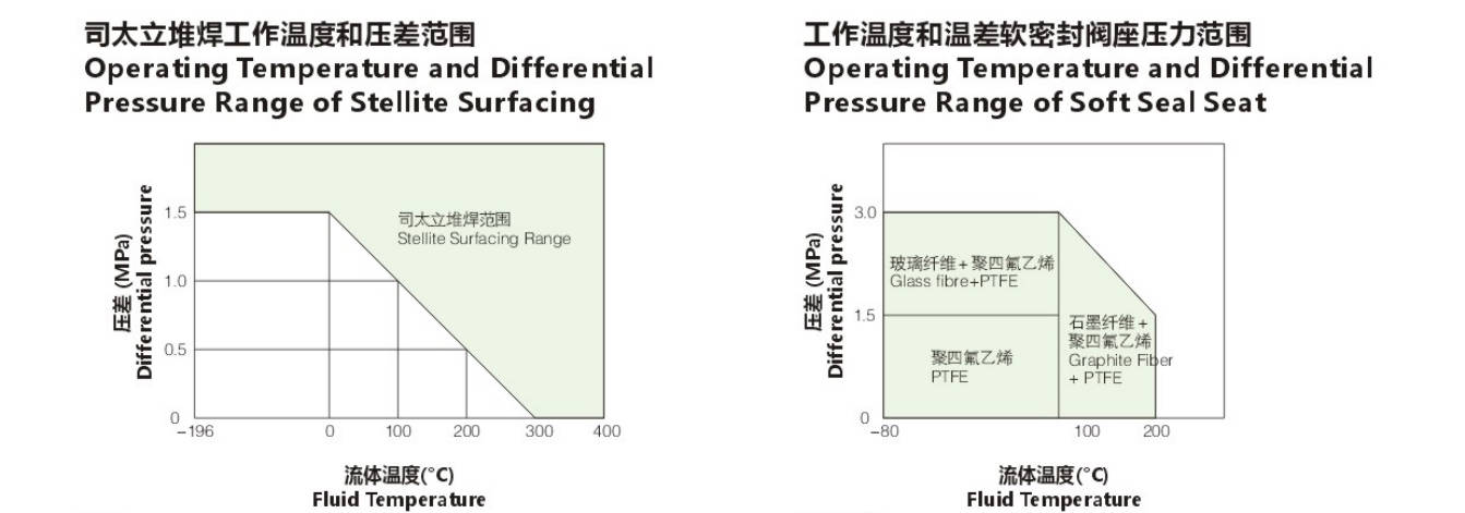
1.Hardening treatment: starlite surfacing or 440B hardening.
2.It is used for cavitation, flash evaporation of forbidden oil or other occasions with closing requirements. Regardless of the working temperature and pressure difference, it is recommended to surfacing stailai alloy.
3.It is suggested that using 440B when the temperature of cavitation, flash or water is over 100 ℃.
Remark:
1.It is recommended to use metal seal when the occasions are saturated steam, hot water, or may cause corrosion and contain impurities.
2.It is used for soft seal by glass fiber and PTFE when treating oil prohibition.
Model Selection Parameter Table
Rated Flow Cv Value
| Seat Diameter (mm) | 10 | 12 | 15 | 20 | 25 | 32 | 40 | 50 | 65 | 80 | 100 | 125 | 150 | 200 |
|---|
| Equal Percentage | 1.6 | 2.5 | 4 | 6.3 | 10 | 17 | 24 | 40 | 63 | 100 | 160 | 250 | 400 | 630 |
| Straight | 1.8 | 2.8 | 4.4 | 6.9 | 11 | 17.6 | 27.5 | 44 | 69 | 110 | 176 | 275 | 440 | 690 |
Nominal Diameter / Stroke / Optional Coefficient Of Flow Cv
(★ Standard Type • Recommended Type ○ Customized Type)
| Nominal Diameter | Stroke | 10 | 12 | 15 | 20 | 25 | 32 | 40 | 50 | 65 | 80 | 100 | 125 | 150 | 200 |
|---|
| DN20 | 16 mm | ● | ● | ● | ★ | | | | | | | | | | |
| DN25 | 16 mm | ● | ● | ● | ● | ★ | | | | | | | | | |
| DN32 | 25 mm | ○ | ○ | ○ | ○ | ○ | ★ | | | | | | | | |
| DN40 | 25 mm | | ○ | ○ | ○ | ○ | ● | ★ | | | | | | | |
| DN50 | 25 mm | | | ○ | ○ | ○ | ● | ● | ★ | | | | | | |
| DN65 | 40 mm | | | | | | ○ | ○ | ○ | ★ | | | | | |
| DN80 | 40 mm | | | | | | ○ | ○ | ○ | ● | ★ | | | | |
| DN100 | 40 mm | | | | | | ○ | ○ | ○ | ● | ● | ★ | | | |
| DN125 | 60 mm | | | | | | | | ○ | ○ | ○ | ★ | | | |
| DN150 | 60 mm | | | | | | | | | ○ | ○ | ● | ★ | | |
| DN200 | 60 mm | | | | | | | | | ○ | ○ | ● | ● | ★ | |
Pneumatic Actuator Diaphragm Active Area Ae
| Model | ZJHA/B-22 | ZJHA/B-23 | ZJHA/B-34 | ZJHA/B-45 |
|---|
| Active Area Ae (cm²) | 350 | 350 | 560 | 900 |
Allowable Pressure Differential of Metal Seal (MPa)
| Action | Range of Spring | 10 | 12 | 15 | 20 | 25 | 32 | 40 | 50 | 65 | 80 | 100 | 125 | 150 | 200 |
|---|
| Open | 20–100 kPa | 4.46 | 3.09 | 1.98 | 1.16 | 0.70 | 0.44 | 0.28 | 0.18 | 0.17 | 0.11 | 0.07 | 0.07 | 0.05 | 0.03 |
| Open | 40–200 kPa | 6.4 | 6.4 | 5.94 | 3.34 | 2.14 | 1.31 | 0.84 | 0.53 | 0.51 | 0.33 | 0.21 | 0.22 | 0.15 | 0.09 |
| Open | 80–240 kPa | 6.4 | 6.4 | 6.4 | 6.4 | 4.99 | 3.05 | 1.95 | 1.25 | 1.18 | 0.78 | 0.50 | 0.51 | 0.36 | 0.21 |
| Close | 20–100 kPa | 6.4 | 6.19 | 3.96 | 2.23 | 2.14 | 0.87 | 0.56 | 0.35 | 0.34 | 0.22 | 0.14 | 0.15 | 0.10 | 0.06 |
| Close | 40–200 kPa | 6.4 | 6.4 | 6.4 | 6.4 | 6.4 | 5.86 | 3.64 | 2.30 | 2.21 | 1.43 | 0.91 | 0.95 | 0.66 | 0.37 |
| Close | 80–240 kPa | 6.4 | 6.4 | 6.4 | 6.4 | 6.4 | 6.4 | 5.04 | 3.18 | 3.06 | 1.98 | 1.26 | 1.32 | 0.92 | 0.52 |
High Precision Flow Characteristic of Valve
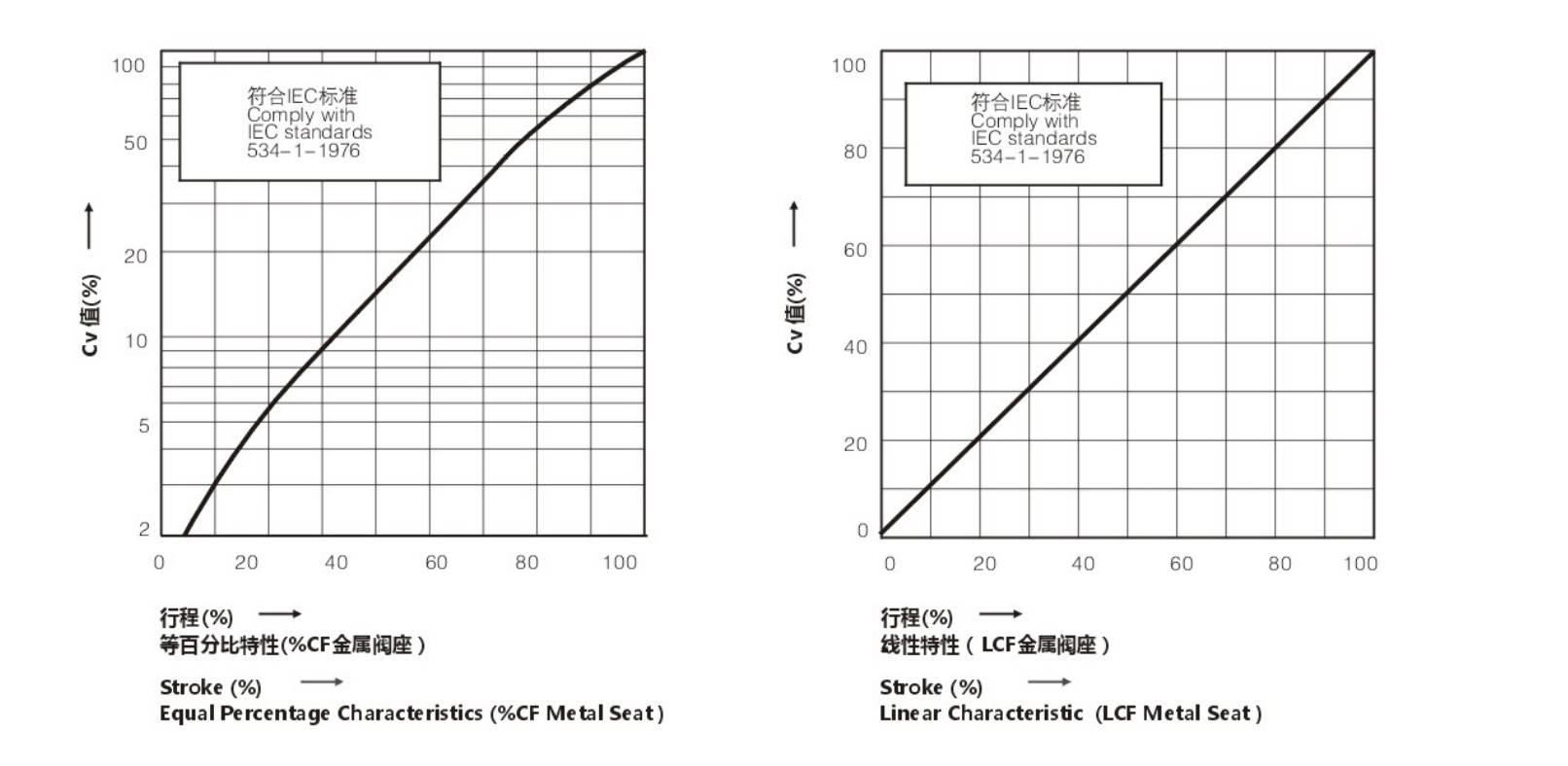
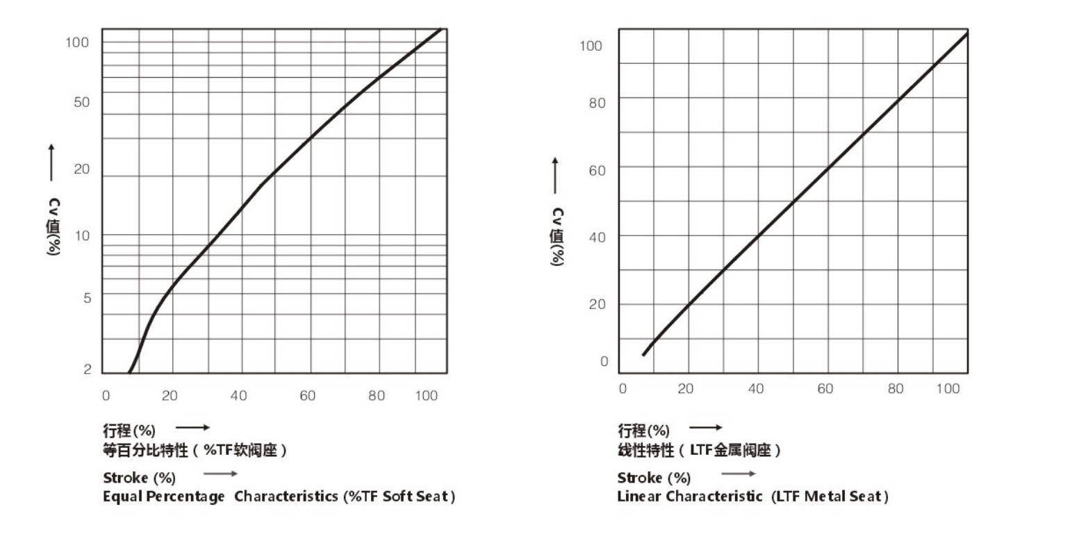
The Size of Control Valve and Hole Shrinkage Internals & Trip; Rated Cv.
| Valve Size | Core Size (inch/mm) | Rated Stroke (mm) | Eq 10% | Eq 25% | Eq 50% | Eq 75% | Eq 100% | St 10% | St 25% | St 50% | St 75% | St 100% |
|---|
| 3/4 (20) | 1/4 (8) | 16 | 0.09 | 0.17 | 0.34 | 0.95 | 1.87 | 0.27 | 0.68 | 1.09 | 1.49 | 2.10 |
| 3/4 (20) | 3/8 (10) | 16 | 0.14 | 0.27 | 0.53 | 1.48 | 2.92 | 0.42 | 1.06 | 1.69 | 2.32 | 3.27 |
| 3/4 (20) | 1/2 (15) | 16 | 0.22 | 0.43 | 0.85 | 2.37 | 4.67 | 0.67 | 1.66 | 2.65 | 3.65 | 5.13 |
| 3/4 (20) | 3/4 (20) | 16 | 0.34 | 0.68 | 1.35 | 3.74 | 7.35 | 1.05 | 2.60 | 4.16 | 5.72 | 8.05 |
| 1 (25) | 1/2 (15) | 16 | 0.22 | 0.43 | 0.85 | 2.37 | 4.67 | 0.67 | 1.66 | 2.56 | 3.65 | 5.13 |
| 1 (25) | 3/4 (20) | 16 | 0.34 | 0.68 | 1.35 | 3.74 | 7.35 | 1.05 | 2.60 | 4.16 | 5.72 | 8.05 |
| 1 (25) | 1 (25) | 16 | 0.55 | 1.08 | 2.14 | 5.93 | 11.67 | 1.67 | 4.15 | 6.64 | 9.11 | 12.84 |
| 1-1/4 (32) | 3/4 (20) | 25 | 0.34 | 0.68 | 1.35 | 3.74 | 7.35 | 1.05 | 2.60 | 4.16 | 5.72 | 8.05 |
| 1-1/4 (32) | 1 (25) | 25 | 0.55 | 1.08 | 2.14 | 5.93 | 11.67 | 1.67 | 4.15 | 6.64 | 9.11 | 12.84 |
| 1-1/4 (32) | 1-1/4 (32) | 25 | 0.87 | 1.73 | 3.42 | 9.49 | 18.67 | 2.67 | 6.63 | 10.62 | 14.58 | 20.54 |
| 1-1/2 (40) | 1 (25) | 25 | 0.55 | 1.08 | 2.14 | 5.93 | 11.67 | 1.67 | 4.15 | 6.64 | 9.11 | 12.84 |
| 1-1/2 (40) | 1-1/4 (32) | 25 | 0.87 | 1.73 | 3.42 | 9.49 | 18.67 | 2.67 | 6.63 | 10.62 | 14.58 | 20.54 |
| 1-1/2 (40) | 1-1/2 (40) | 25 | 1.36 | 2.72 | 5.35 | 14.82 | 29.17 | 4.17 | 10.37 | 16.59 | 22.79 | 32.09 |
| 2 (50) | 1-1/4 (32) | 25 | 0.87 | 1.73 | 3.42 | 9.49 | 18.67 | 2.67 | 6.63 | 10.62 | 14.58 | 20.54 |
| 2 (50) | 1-1/2 (40) | 25 | 1.36 | 2.72 | 5.35 | 14.82 | 29.17 | 4.17 | 10.37 | 16.59 | 22.79 | 32.09 |
| 2 (50) | 2 (50) | 25 | 2.18 | 4.32 | 8.54 | 23.71 | 46.68 | 6.67 | 16.58 | 26.56 | 36.46 | 51.35 |
| 2-1/2 (65) | 1-1/2 (40) | 40 | 1.36 | 2.72 | 5.35 | 14.82 | 29.17 | 4.17 | 10.37 | 16.59 | 22.79 | 32.09 |
| 2-1/2 (65) | 2 (50) | 40 | 2.18 | 4.32 | 8.54 | 23.71 | 46.68 | 6.67 | 16.58 | 26.56 | 36.46 | 51.35 |
| 2-1/2 (65) | 2-1/2 (65) | 40 | 3.34 | 6.81 | 13.45 | 37.35 | 73.52 | 10.47 | 20.01 | 41.63 | 57.17 | 80.52 |
| 3 (80) | 2 (50) | 40 | 2.18 | 4.32 | 8.54 | 23.71 | 46.68 | 6.67 | 16.58 | 26.56 | 36.46 | 51.35 |
| 3 (80) | 2-1/2 (65) | 40 | 3.34 | 6.81 | 13.45 | 37.35 | 73.52 | 10.47 | 26.01 | 41.63 | 57.17 | 80.52 |
| 3 (80) | 3 (80) | 40 | 5.45 | 10.81 | 21.36 | 59.28 | 116.7 | 16.69 | 41.46 | 66.37 | 91.14 | 128.4 |
| 4 (100) | 2-1/2 (65) | 40 | 3.34 | 6.81 | 13.45 | 37.35 | 73.52 | 10.47 | 26.01 | 41.63 | 57.17 | 80.52 |
| 4 (100) | 3 (80) | 40 | 5.45 | 10.81 | 21.36 | 59.28 | 116.7 | 16.69 | 41.46 | 66.37 | 91.14 | 128.4 |
| 4 (100) | 4 (100) | 40 | 8.72 | 17.29 | 34.17 | 94.85 | 186.7 | 26.70 | 66.34 | 106.2 | 145.8 | 205.4 |
| 5 (125) | 3 (80) | 60 | 13.62 | 10.81 | 21.36 | 59.28 | 116.7 | 16.69 | 41.46 | 66.37 | 91.14 | 128.4 |
| 5 (125) | 4 (100) | 60 | 21.80 | 17.29 | 34.17 | 94.85 | 186.7 | 26.70 | 66.34 | 106.2 | 145.8 | 205.4 |
| 5 (125) | 5 (125) | 60 | 13.62 | 27.06 | 53.40 | 148.2 | 291.7 | 41.72 | 103.7 | 165.9 | 227.9 | 320.9 |
| 6 (150) | 4 (100) | 60 | 21.80 | 17.29 | 34.17 | 94.85 | 186.7 | 26.70 | 66.34 | 106.2 | 145.8 | 205.4 |
| 6 (150) | 5 (125) | 60 | 13.62 | 27.06 | 53.40 | 148.2 | 291.7 | 41.72 | 103.7 | 165.9 | 227.9 | 320.9 |
| 6 (150) | 6 (150) | 60 | 21.80 | 43.23 | 65.42 | 237.1 | 466.8 | 66.75 | 165.85 | 265.5 | 364.6 | 513.5 |
| 8 (200) | 5 (125) | 60 | 13.62 | 27.06 | 53.40 | 148.2 | 291.7 | 41.72 | 103.7 | 165.9 | 227.9 | 320.9 |
| 8 (200) | 6 (150) | 60 | 21.80 | 43.23 | 85.42 | 237.1 | 466.8 | 66.75 | 165.85 | 265.5 | 364.6 | 513.5 |
| 8 (200) | 8 (200) | 60 | 34.34 | 68.08 | 134.5 | 373.5 | 735.2 | 104.7 | 260.1 | 416.3 | 571.7 | 805.2 |
Material of Valve and Components · Range of Using Temperature · Allowable Leakage of Seat
Body Material: Carbon Steel
| Item | Material / Treatment | Column 1 | Column 2 | Column 3 |
|---|
| Body Material | | SCPH2 / A216-WCB | SCPH21 / A217-WC5 | SCPL1 / A352-LCB |
| Core | Material | SUS304 / 316 | SUS304 / 316 | SUS304 / 316 |
| Treatment | – | R.TFE | SS / SF |
| Seat | Material | SUS304 / 316 | SUS304 / 316 | SUS304 / 316 |
| Treatment | – | – | SS / SF |
| Guide Sleeve | Material | SUS420 | SUS420 | SUS420 |
| Treatment | HT | HT | HT |
| Gasket | Material | SUS316L | SUS316L | SUS316L |
| Allowable Leakage of Seat | ANSI | CLASS IV | CLASS VI | CLASS IV |
| Rated CvX | 0.01% | Bubble-Tight | 0.01% |
Operating Temperature (°C)
| Body Type | Column 1 | Column 2 | Column 3 |
|---|
| SCPH2 / WCB Body | −17 ~ +425 | −17 ~ +230 | −17 ~ +425 |
| SCPH21 / WC6 Body | −17 ~ +566 | −17 ~ +230 | −17 ~ +566 |
| SCPL1 / LCB Body | −45 ~ +350 | −45 ~ +270 | −45 ~ +350 |
Material of Valve and Components · Range of Using Temperature · Allowable Leakage of Seat
Body Material: Stainless Steel
| Item | Material / Treatment | Column 1 | Column 2 | Column 3 |
|---|
| Body Material | | SCS13A / CF8 | SCS14A / CF8M | SCS16A / CF3M |
| Core | Material | SUS304 / 316 / 316L | SUS304 / 316 | SUS304 / 316 / 316L |
| Treatment | – | R.TFE | SS / SF |
| Seat | Material | SUS304 / 316 / 316L | SUS304 / 316 / 316L | SUS304 / 316 / 316L |
| Treatment | – | – | SS / SF |
| Guide Sleeve | Material | SUS304 / 316 / 316L | SUS304 / 316 / 316L | SUS304 / 316 / 316L |
| Treatment | – | R.TFE | ST |
| Gasket | Material | SUS316L | SUS316L | SUS316L |
| Allowable Leakage of Seat | ANSI | CLASS IV | CLASS VI | CLASS IV |
| Rated CvX | 0.01% | Bubble-Tight | 0.01% |
| Operating Temperature (°C) | | −196 ~ +566 | −45 ~ +230 | −196 ~ +566 |
R.TFE: Reinforced PTFE | HT: Heat Treatment | ST: Surfacing Stellite Alloy | SS: Partial Surfacing Stellite Alloys | SF: All Surfacing Stellite Alloys
Allowable Differential Pressure
Multi-spring Diaphragm Actuator
Unit: MPa
| Actuator Specification | Air Pressure (kPa) | Spring Range (kPa) | 3/4 (20) | 1 (25) | 1 1/4 (32) | 1 1/2 (40) | 2 (50) | 2 1/2 (65) | 3 (80) | 4 (100) | 5 (125) | 6 (150) | 8 (200) |
|---|
| ZJHA/B-22 | 140 | 20–100 | 1.17 | 0.75 | – | – | – | – | – | – | – | – | – |
| ZJHA/B-22 | 240 | 40–200 | 2.73 | 1.75 | – | – | – | – | – | – | – | – | – |
| ZJHA/B-22 | 300 | 80–240 | 5.85 | 3.75 | – | – | – | – | – | – | – | – | – |
| ZJHA/B-23 | 140 | 20–100 | 1.64 | 1.05 | 0.63 | 0.40 | 0.26 | – | – | – | – | – | – |
| ZJHA/B-23 | 240 | 40–200 | 3.82 | 2.45 | 1.49 | 0.96 | 0.61 | – | – | – | – | – | – |
| ZJHA/B-23 | 300 | 80–240 | 8.19 | 5.24 | 3.19 | 2.05 | 1.31 | – | – | – | – | – | – |
| ZJHA/B-34 | 140 | 20–100 | – | – | 1.02 | 0.66 | 0.42 | 0.24 | 0.16 | 0.10 | – | – | – |
| ZJHA/B-34 | 240 | 40–200 | – | – | 2.38 | 1.53 | 0.98 | 0.58 | 0.38 | 0.24 | – | – | – |
| ZJHA/B-34 | 300 | 80–240 | – | – | 5.12 | 3.28 | 2.10 | 1.24 | 0.82 | 0.52 | – | – | – |
| ZJHA/B-45 | 140 | 20–100 | – | – | – | – | – | 0.40 | 0.26 | 0.17 | 0.11 | 0.07 | 0.02 |
| ZJHA/B-45 | 240 | 40–200 | – | – | – | – | – | 0.93 | 0.61 | 0.39 | 0.25 | 0.17 | 0.07 |
| ZJHA/B-45 | 300 | 80–240 | – | – | – | – | – | 1.98 | 1.32 | 0.84 | 0.54 | 0.37 | 0.16 |
381L Series of Electronic Actuator
Unit: MPa
| Model / Specification | Voltage Rating | 3/4 (20) | 1 (25) | 1 1/4 (32) | 1 1/2 (40) | 2 (50) | 2 1/2 (65) | 3 (80) | 4 (100) | 5 (125) | 6 (150) | 8 (200) |
|---|
| 381LSA-08 | 110V / 220V / 380V | 2.38 | 1.52 | 0.93 | 0.59 | 0.38 | – | – | – | – | – | – |
| 381LSA-08 | 110V / 220V / 380V | 1.91 | 1.22 | 0.74 | 0.47 | 0.30 | – | – | – | – | – | – |
| 381LSA-20 | 110V / 220V / 380V | 4.77 | 3.05 | 1.86 | 1.19 | 0.76 | 0.45 | – | – | – | – | – |
| 381LSA-20 | 110V / 220V / 380V | 3.82 | 2.44 | 1.49 | 0.95 | 0.61 | 0.36 | – | – | – | – | – |
| 381LSB-30 | 110V / 220V / 380V | – | – | 2.79 | 1.79 | 1.14 | 0.67 | 1.21 | 0.28 | 0.18 | 0.12 | 0.03 |
| 381LSB-30 | 110V / 220V / 380V | – | – | 2.23 | 1.43 | 0.91 | 0.54 | 0.96 | 0.22 | 0.14 | 0.10 | 0.02 |
| 381LSB-50 | 110V / 220V / 380V | – | – | 4.66 | 2.98 | 1.91 | 1.13 | 1.51 | 0.47 | 0.30 | 0.21 | 0.08 |
| 381LSB-50 | 110V / 220V / 380V | – | – | 3.73 | 2.38 | 1.52 | 0.90 | 1.20 | 0.38 | 0.24 | 0.16 | 0.06 |
| 381LSC-65 | 110V / 220V / 380V | – | – | – | – | – | 1.35 | 2.34 | 0.57 | 0.36 | 0.25 | 0.11 |
| 381LSC-65 | 110V / 220V / 380V | – | – | – | – | – | 1.08 | 1.87 | 0.45 | 0.29 | 0.20 | 0.08 |
| 381LSC-99 | 110V / 220V / 380V | – | – | – | – | – | 2.26 | 2.92 | 0.95 | 0.61 | 0.42 | 0.20 |
| 381LSC-99 | 110V / 220V / 380V | – | – | – | – | – | 1.80 | 2.33 | 0.76 | 0.48 | 0.33 | 0.15 |
| 381LSC-160 | 110V / 220V / 380V | – | – | – | – | – | – | – | – | 0.97 | 0.67 | 0.35 |
| 381LSC-160 | 110V / 220V / 380V | – | – | – | – | – | – | – | – | 0.78 | 0.54 | 0.27 |
Outline Drawing:
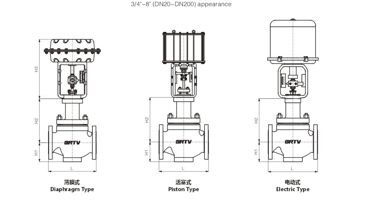
Appearance Dimension
Unit: mm
| DN (inch) | DN (mm) | ANSI150 PN16/25 (GB/T12221) | ANSI150 PN16/25 (GB/T17213.3) | ANSI300 PN40 (GB/T17213.3) | ANSI600 PN64/100 (GB/T17213.3) | H1 | H2 | H3 | Electrical Actuator | Pneumatic Actuator |
|---|
| 3/4 | 20 | 150 | 184 | 194 | 206 | 40 | 135 | 274 | 381LSA-20 | ZJHA/B-22 |
| 1 | 25 | 160 | 184 | 197 | 210 | 43 | 146 | 274 | 381LSA-20 | ZJHA/B-22 |
| 1 1/4 | 32 | 180 | 210 | 235 | 251 | 45 | 163 | 302 | 381LSB-30 | ZJHA/B-23 |
| 1 1/2 | 40 | 200 | 222 | 235 | 251 | 56 | 163 | 302 | 381LSB-30 | ZJHA/B-23 |
| 2 | 50 | 230 | 254 | 267 | 286 | 73 | 165 | 302 | 381LSB-30 | ZJHA/B-23 |
| 2 1/2 | 65 | 290 | 276 | 292 | 311 | 83 | 217 | 375 | 381LSB-50 | ZJHA/B-34 |
| 3 | 80 | 310 | 298 | 317 | 337 | 102 | 235 | 375 | 381LSB-50 | ZJHA/B-34 |
| 4 | 100 | 350 | 352 | 368 | 394 | 110 | 236 | 375 | 381LSB-50 | ZJHA/B-34 |
| 5 | 125 | 400 | 402 | 425 | 500 | 146 | 340 | 465 | 381LSC-99 | ZJHA/B-45 |
| 6 | 150 | 480 | 451 | 473 | 508 | 170 | 340 | 465 | 381LSC-99 | ZJHA/B-45 |
| 8 | 200 | 600 | 543 | 568 | 610 | 220 | 383 | 465 | 381LSC-99 | ZJHA/B-45 |
Manufacturing Process
Step 1: Order and Design
Confirm customer requirements such as size, pressure rating, material, leakage class, and actuator type. Based on the application conditions, prepare drawings, BOM, and technical specifications for the Single Seat Control Valve.
Step 2: Forging & Casting
Select suitable raw materials for body, bonnet, trim, and other pressure-bearing parts. Valve body and bonnet for the Single Seat Control Valve are produced by casting or forging according to design and pressure requirements, followed by material inspection.
Step 3: Machining
Carry out precision machining on the body, bonnet, seat ring, plug, stem, and flange faces. Critical dimensions, sealing surfaces, and internal flow passages of the Single Seat Control Valve must be machined accurately to ensure good control performance and shutoff capability.
Step 4: Assembly
Assemble valve body, seat, plug, stem, bonnet, packing, and actuator in accordance with assembly procedures. During Single Seat Control Valve assembly, special attention is paid to stem alignment, seating accuracy, and smooth travel movement.
Step 5: Testing & Quality Assurance
Perform pressure test, seat leakage test, stroke calibration, and functional inspection. Each Single Seat Control Valve must pass dimensional checks and performance testing before release to ensure reliability and compliance with standards.
Step 6: Painting and Finishing
After final inspection, clean the valve surface, apply primer and top coating, then complete nameplate marking, packaging, and shipment preparation.
Applications
The single seat control valve is composed of a valve body and an electric actuator. It can receive 4-20mA or pulse signals to achieve automatic control of parameters such as flow, pressure, temperature, and liquid level. Its power supply voltage is generally 220V or 380V. The flow characteristics include linear, equal percentage, and quick opening. Compared with pneumatic regulating valves, electric regulating valves have the advantages of energy saving, environmental protection, and convenient installation, and are widely used in industrial automation fields such as power, chemical industry, metallurgy, environmental protection, and water treatment.
These valves are widely used in:
Agriculture and Irrigation
Factory Environment
Why Choose Us
Superior Quality

Our valves are manufactured using premium materials and undergo rigorous quality testing to ensure reliable performance in demanding industrial applications.
Advanced Technology

Equipped with state-of-the-art CNC machining centers and precision manufacturing equipment, we deliver valves with exceptional accuracy and consistency.
Competitive Pricing

Through optimized manufacturing processes and bulk material procurement, we offer high-quality valves at competitive prices without compromising on quality.
Expert Support

Our experienced technical team provides comprehensive support from product selection to after-sales service, ensuring optimal valve performance for your specific application.