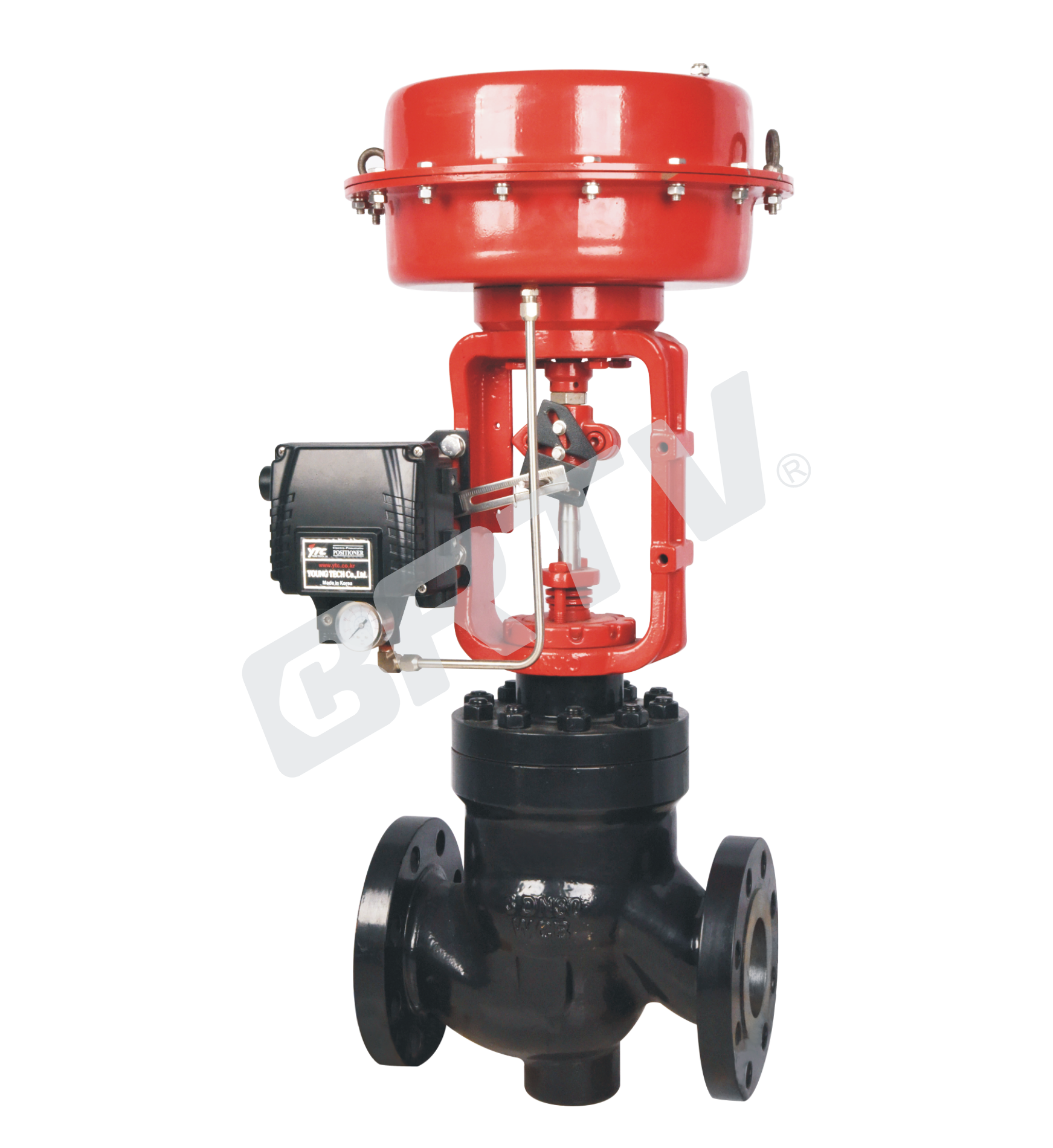
Cage Type Single Seat Control Valve
cage type single seat control valve is a single seat control valve with high performance, and is suitable for occasion of flash distillation and cavitation by high differential pressure. The strong sleeve can keep body from flash and cavitation damage. The body and fluid channel are s–shaped, with small pressure drop loss, large flow, adjustable range.
The valve core has large guiding area and good vibration resistance. The control valve is equipped with multi–spring diaphragm actuator or electric actuator, and has compact structure, large output torque.
Standard Specification
| Manner | Straight Through Casting Ball Valve |
|---|
| Nominal Diameter | 25, 32, 40, 50, 65, 80, 100, 150, 200 mm |
| Nominal Pressure | ANSI Class 150, 300, 600; JIS 10K, 20K, 30K, 40K; PN 1.6, 4.0, 6.4 MPa |
| Type of Connection | Flange Type: FF, RF, RJ, TG, MFM; Weld Type: SW (40–50 mm), BW (65–200 mm) |
| Material of Body and Bonnet | SCPH2/WCB, SCPH21/WC6, SCS13A/CF8, SCS14A/CF8M, SCS16A/CF3M, Ti |
| Bonnet Manner | Normal Temperature (P): −17 ~ +230 ℃; Elongation Type I (EI): −45 ~ −17 ℃, +230 ~ +566 ℃; Elongation Type II (EII): −100 ~ −45 ℃ |
| Gland Manner | Screw Fastening Type |
| Packing | V-type PTFE Packing, Graphite Packing |
| Gasket | Plain Type, Zigzag Type / Stainless Steel (SUS304, SUS316, SUS316L) and other Alloys |
| Surface Coating | Blue (Epoxy). When the valve body material is stainless steel, coating is not applied |
Cv Valve and Stroke
| Nominal Diameter | Seat Diameter | Rated Cv | Rated Stroke |
|---|
| 25 | 15 | 4.0 | 16 |
| 25 | 20 | 6.3 | 16 |
| 25 | 25 | 10 | 16 |
| 32 | 15 | 4.0 | 16 |
| 32 | 25 | 10 | 16 |
| 32 | 32 | 17 | 16 |
| 40 | 15 | 4.0 | 25 |
| 40 | 20 | 6.3 | 25 |
| 40 | 25 | 12 | 25 |
| 50 | 20 | 6.3 | 25 |
| 50 | 25 | 12 | 25 |
| 50 | 32 | 21 | 25 |
| 65 | 25 | 12 | 40 |
| 65 | 32 | 21 | 40 |
| 65 | 40 | 30 | 40 |
| 80 | 32 | 21 | 40 |
| 80 | 40 | 30 | 40 |
| 80 | 50 | 50 | 40 |
| 100 | 40 | 30 | 40 |
| 100 | 50 | 50 | 40 |
| 100 | 65 | 85 | 40 |
| 150 | 65 | 85 | 60 |
| 150 | 80 | 125 | 60 |
| 150 | 100 | 200 | 60 |
| 200 | 80 | 125 | 60 |
| 200 | 100 | 200 | 60 |
| 200 | 125 | 310 | 60 |
Actuator
| Item | Pneumatic Diaphragm Type | Cylinder Piston Type | Electronic Type | Intelligent Type |
|---|
| Model | ZJHA/B | ZTCLS / ZTCL | 381 Series | ZM Series |
| Structure | Multiple Springs Type | Single Action / Double Action | — | — |
| Service | Regulation | Regulation | Regulation | Regulation |
| Supply Gas Pressure / Supply Voltage | Supply Gas Pressure (spring range): 140(20–100) kPa / 160(20–100) kPa / 280(80–240) kPa / 400(80–240) kPa | Supply Gas Pressure: 300–500 kPa | Voltage: 220/380 V 50 Hz; Input Signal: 4–20 mA DC | Voltage: 220/380 V 50 Hz; Input Signal: 4–20 mA DC |
| Connector | Air Piping: RC1/4 | Air Piping: G1/8, G1/4, G1/2, G3/8 | Wiring: PG13.5 | Wiring: PG13.5 |
| Positive Action | Adding Pressure – Valve Will Be Closed | Adding Pressure – Valve Will Be Closed | Inputting the Signal – Valve Will Be Closed | Inputting the Signal – Valve Will Be Closed |
| Negative Action | Adding Pressure – Valve Will Be Opened | Adding Pressure – Valve Will Be Opened | Inputting the Signal – Valve Will Be Opened | Inputting the Signal – Valve Will Be Opened |
| Hysteresis | ≤1% FS (with positioner) / ≤3% FS (no positioner) / ≤5% FS (HA1 type) | ≤1% FS (with positioner) / ≤3% FS (no positioner) | =1% FS | =1% FS |
| Intrinsic Error | ≤1% FS (with positioner) / ≤2% FS (HA1 type) / ≤5% FS (no positioner) | ≤1% FS (with positioner) / ≤5% FS (no positioner) | =1% FS | =1% FS |
| Ambient Temperature | Standard: −30 ~ +70 °C; High Temperature Type: 0 ~ +100 °C; Low Temperature Type: −40 ~ +40 °C | Standard: −20 ~ +60 °C; High Temperature Type: 0 ~ +100 °C; Low Temperature Type: −50 ~ +60 °C | −20 ~ +70 °C | −25 ~ +70 °C |
| Painting Color | Blue Scale 10B5/10 | Blue Scale 10B5/10 | — | — |
| Accessory | Positioner / Air Filtration / Pressure Reducing Valve / Transmitter / Handwheel | Positioner / Air Filtration / Pressure Reducing Valve / Transmitter / Handwheel | Integrated Type | Integrated Type |
Model Selection Parameter Table
Rated Flow Cv Value
| Seat Diameter (mm) | 25 | 32 | 40 | 50 | 65 | 80 | 100 | 125 | 150 | 200 |
|---|
| Equal Percentage Cv | 10 | 17 | 24 | 40 | 63 | 100 | 160 | 250 | 400 | 630 |
| Straight Cv | 11 | 17.6 | 27.5 | 44 | 69 | 110 | 176 | 275 | 440 | 690 |
Optional Coefficient Of Flow Cv
(★ standard Type • recommend Type ○ customized Type)
| Nominal Diameter | Stroke | 25 | 32 | 40 | 50 | 65 | 80 | 100 | 125 | 150 | 200 |
|---|
| DN25 | 16 mm | ★ | | | | | | | | | |
| DN32 | 16 mm | ○ | ★ | | | | | | | | |
| DN40 | 25 mm | ○ | • | ★ | | | | | | | |
| DN50 | 25 mm | ○ | • | • | ★ | | | | | | |
| DN65 | 25 mm | | ○ | ○ | ○ | ★ | | | | | |
| DN80 | 40 mm | | ○ | ○ | ○ | • | ★ | | | | |
| DN100 | 40 mm | | ○ | ○ | ○ | • | • | ★ | | | |
| DN125 | 40 mm | | | | | ○ | ○ | ○ | ★ | | |
| DN150 | 60 mm | | | | | | ○ | ○ | • | ★ | |
| DN200 | 60 mm | | | | | | ○ | ○ | • | • | ★ |
| DN250 | 60 mm | | | | | | | | ○ | • | • |
| DN300 | 100 mm | | | | | | | | | ○ | • |
Pneumatic Actuator Diaphragm Active Area Ae (cm²)
| Model | Active Area |
|---|
| ZHA/B-22 | 350 |
| ZHA/B-23 | 350 |
| ZHA/B-34 | 560 |
| ZHA/B-45 | 900 |
Allowable Pressure Differential of Metal Seal (MPa)
| Range of Spring | 25 | 32 | 40 | 50 | 65 | 80 | 100 | 125 | 150 | 200 |
|---|
| 20–100 KPa | 3 | 2.25 | 2.25 | 1.95 | 2.36 | 2.04 | 1.67 | 1.41 | 1.41 | 1.14 |
| 40–200 KPa | 6.4 | 6.4 | 6.4 | 6.4 | 6.4 | 6.4 | 6.4 | 6.4 | 6.4 | 6.4 |
| 80–240 KPa | 6.4 | 6.4 | 6.4 | 6.4 | 6.4 | 6.4 | 6.4 | 6.4 | 6.4 | 6.4 |
| Range of Spring | 25 | 32 | 40 | 50 | 65 | 80 | 100 | 125 | 150 | 200 |
|---|
| 20–100 KPa | 1.5 | 1.13 | 1.13 | 0.98 | 1.18 | 1.02 | 0.84 | 0.71 | 0.71 | 0.57 |
| 40–200 KPa | 4.5 | 3.38 | 3.38 | 2.93 | 3.54 | 3.06 | 2.51 | 2.12 | 2.12 | 1.71 |
| 80–240 KPa | 6.4 | 6.4 | 6.4 | 6.4 | 6.4 | 6.4 | 5.85 | 4.94 | 4.94 | 4 |
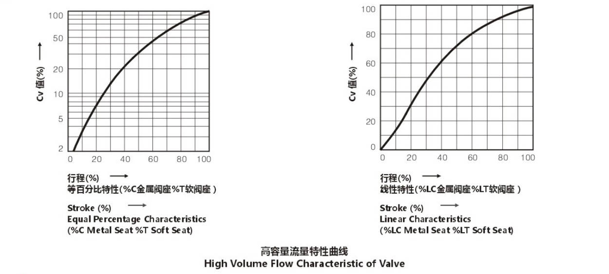
Typical Flow Characteristic of Valve
The Material of Valve and Components, Range of Using Temperature · Allowable Leakage of Seat
Body Material: Carbon Steel
| Category | Item | Property | SCPH2/A216-WCB | SCPH21/A217-WC6 | SCPL1/A352-LCB |
|---|
| Body Material | Body | Material | SCPH2/A216-WCB | SCPH21/A217-WC6 | SCPL1/A352-LCB |
| Core | Core | Material | SUS304/316 | SUS304/316 | SUS304/316 |
| Core | Core | Treatment | — | R.TFE | SS/SF |
| Seat | Seat | Material | SUS304/316 | SUS304/316 | SUS304/316 |
| Seat | Seat | Treatment | — | — | SS/SF |
| Guide Sleeve | Guide Sleeve | Material | SUS420 | SUS420 | SUS420 |
| Guide Sleeve | Guide Sleeve | Treatment | HT | HT | HT |
| Gasket | Gasket | Material | SUS316L | SUS316L | SUS316L |
| Allowable Leakage of Seat | ANSI | Leakage Class | CLASS IV | CLASS VI | CLASS IV |
| Allowable Leakage of Seat | Rated Cvx | Leakage Rate | 0.01% | Bubble-Tight | 0.01% |
| Operating Temperature (°C) | SCPH2/WCB Body | Temperature Range | −17 ~ +425 | −17 ~ +230 | −17 ~ +425 |
| Operating Temperature (°C) | SCPH21/WC6 Body | Temperature Range | −17 ~ +566 | −17 ~ +230 | −17 ~ +566 |
| Operating Temperature (°C) | SCPL1/LCB Body | Temperature Range | −45 ~ +350 | −45 ~ +230 | −45 ~ +350 |
Body Material: Stainless Steel
| Category | Item | Property | SCS13A/CF8 | SCS14A/CF8M | SCS16A/CF3M |
|---|
| Body Material | Body | Material | SCS13A/CF8 | SCS14A/CF8M | SCS16A/CF3M |
| Core | Core | Material | SUS304/316/316L | SUS304/316 | SUS304/316/316L |
| Core | Core | Treatment | — | R.TFE | SS/SF |
| Seat | Seat | Material | SUS304/316/316L | SUS304/316/316L | SUS304/316/316L |
| Seat | Seat | Treatment | — | — | SS/SF |
| Guide Sleeve | Guide Sleeve | Material | SUS304/316/316L | SUS304/316/316L | SUS304/316/316L |
| Guide Sleeve | Guide Sleeve | Treatment | — | R.TFE | ST |
| Gasket | Gasket | Material | SUS316L | SUS316L | SUS316L |
| Allowable Leakage of Seat | ANSI | Leakage Class | CLASS IV | CLASS VI | CLASS IV |
| Allowable Leakage of Seat | Rated Cvx | Leakage Rate | 0.01% | Bubble-Tight | 0.01% |
| Operating Temperature (°C) | Temperature Range | Range | -196 ~ +566 | -45 ~ +230 | -196 ~ +566 |
R.TFE : Reinforced PTFE HT : Heat Treatment ST : Surfacing Sitalai Alloy SS : Partial Surfacing Sitalai Alloys SF : All Surfacing Sitalai Alloys
Outline Drawing
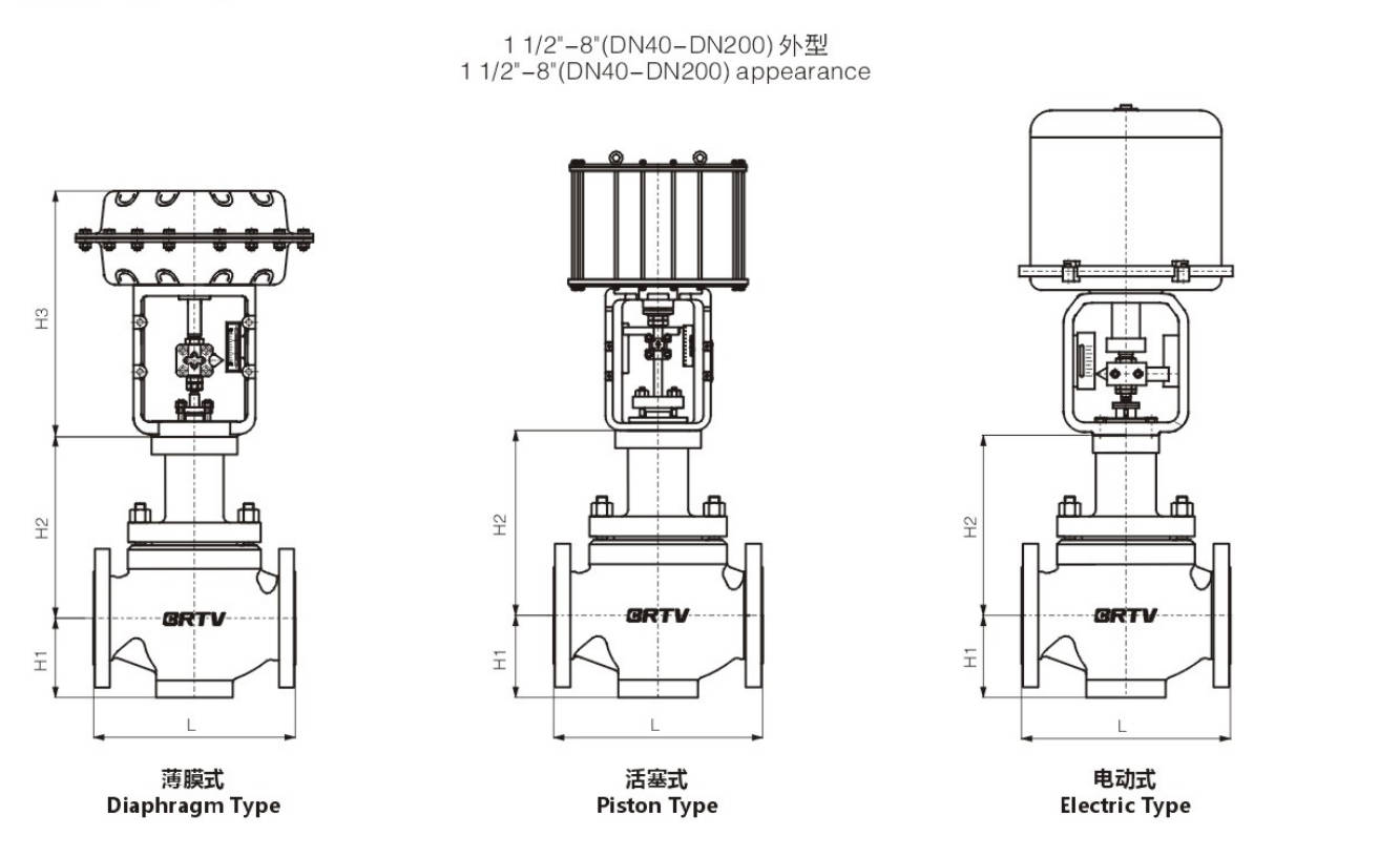
Appearance Dimension
Unit:mm
| DN (inch) | DN (mm) | L ANSI150 (GB/T12221) | L ANSI150 (GB/T17213.3) | L ANSI300 (GB/T17213.3) | L ANSI600 (GB/T17213.3) | H1 | H2 | H3 | Electrical Actuator | Pneumatic Actuator |
|---|
| 1 1/2 | 40 | 200 | 222 | 235 | 251 | 56 | 163 | 302 | 381LSB-30 | ZJHA/B 23 |
| 2 | 50 | 230 | 254 | 267 | 286 | 73 | 165 | 302 | 381LSB-30 | ZJHA/B 23 |
| 2 1/2 | 65 | 290 | 276 | 292 | 311 | 83 | 217 | 375 | 381LSB-50 | ZJHA/B 34 |
| 3 | 80 | 310 | 298 | 317 | 337 | 102 | 235 | 375 | 381LSB-50 | ZJHA/B 34 |
| 4 | 100 | 350 | 352 | 368 | 394 | 110 | 236 | 375 | 381LSB-50 | ZJHA/B 34 |
| 5 | 125 | 400 | 400 | 425 | 500 | 146 | 340 | 465 | 381LSC-99 | ZJHA/B 45 |
| 6 | 150 | 480 | 451 | 473 | 508 | 170 | 340 | 465 | 381LSC-99 | ZJHA/B 45 |
| 8 | 200 | 600 | 543 | 568 | 610 | 220 | 383 | 465 | 381LSC-99 | ZJHA/B 45 |
Manufacturing Process
Step 1: Order and Design
According to the customer’s working conditions, including pressure, temperature, flow coefficient, leakage class, and connection standard, the design of the cage Type single seat control valve is confirmed.
At this stage, valve body material, trim material, actuator type, cage structure, and seat sealing form are selected, and production drawings are released for manufacturing.
Step 2: Forging & Casting
The main pressure-bearing parts, such as valve body, bonnet, and other key components, are produced by casting or forging according to the design requirements of the cage Type single seat control valve.
After casting, rough cleaning, heat treatment, and material inspection are carried out to ensure the blanks meet mechanical property and dimensional requirements.
Step 3: Machining
All main components are machined precisely, including valve body cavity, bonnet connection faces, seat pocket, stem hole, cage, plug, and seat ring.
For the cage Type single seat control valve, special attention is given to the machining accuracy of the cage window, seating surface, and guiding parts, so as to ensure good control performance and shut-off capability.
Step 4: Assembly
After all parts pass inspection, assembly begins. The seat ring, cage, plug, stem, bonnet, packing, gasket, and actuator are installed step by step.
During the assembly of the cage Type single seat control valve, concentricity, stem movement, and actuator-stroke matching are carefully checked to guarantee stable operation.
Step 5: Testing & Quality Assurance
Each cage Type single seat control valve is subjected to pressure test, seat leakage test, air tightness check, stroke calibration, and action performance test.
At the same time, dimensional inspection, material certificate verification, and appearance check are completed to ensure the valve meets technical specifications and quality standards.
Step 6: Painting and Finishing
After testing is completed, the valve surface is cleaned and painted according to the order requirement. Nameplate, tags, and identification marks are fixed, and final protection is applied before packing.
Then the finished valve is packed securely for shipment.
Applications
It is widely used in various industrial processes with wide requirements for pressure drop and temperature range. It can be used for regulating or switching control of multiple liquids or gases independently. The cage type control valve is also widely applied in industries such as petroleum, natural gas, chemical engineering, power, and steel.
These valves are widely used in:
Agriculture and Irrigation
Factory Environment
Why Choose Us
Superior Quality

Our valves are manufactured using premium materials and undergo rigorous quality testing to ensure reliable performance in demanding industrial applications.
Advanced Technology

Equipped with state-of-the-art CNC machining centers and precision manufacturing equipment, we deliver valves with exceptional accuracy and consistency.
Competitive Pricing

Through optimized manufacturing processes and bulk material procurement, we offer high-quality valves at competitive prices without compromising on quality.
Expert Support

Our experienced technical team provides comprehensive support from product selection to after-sales service, ensuring optimal valve performance for your specific application.