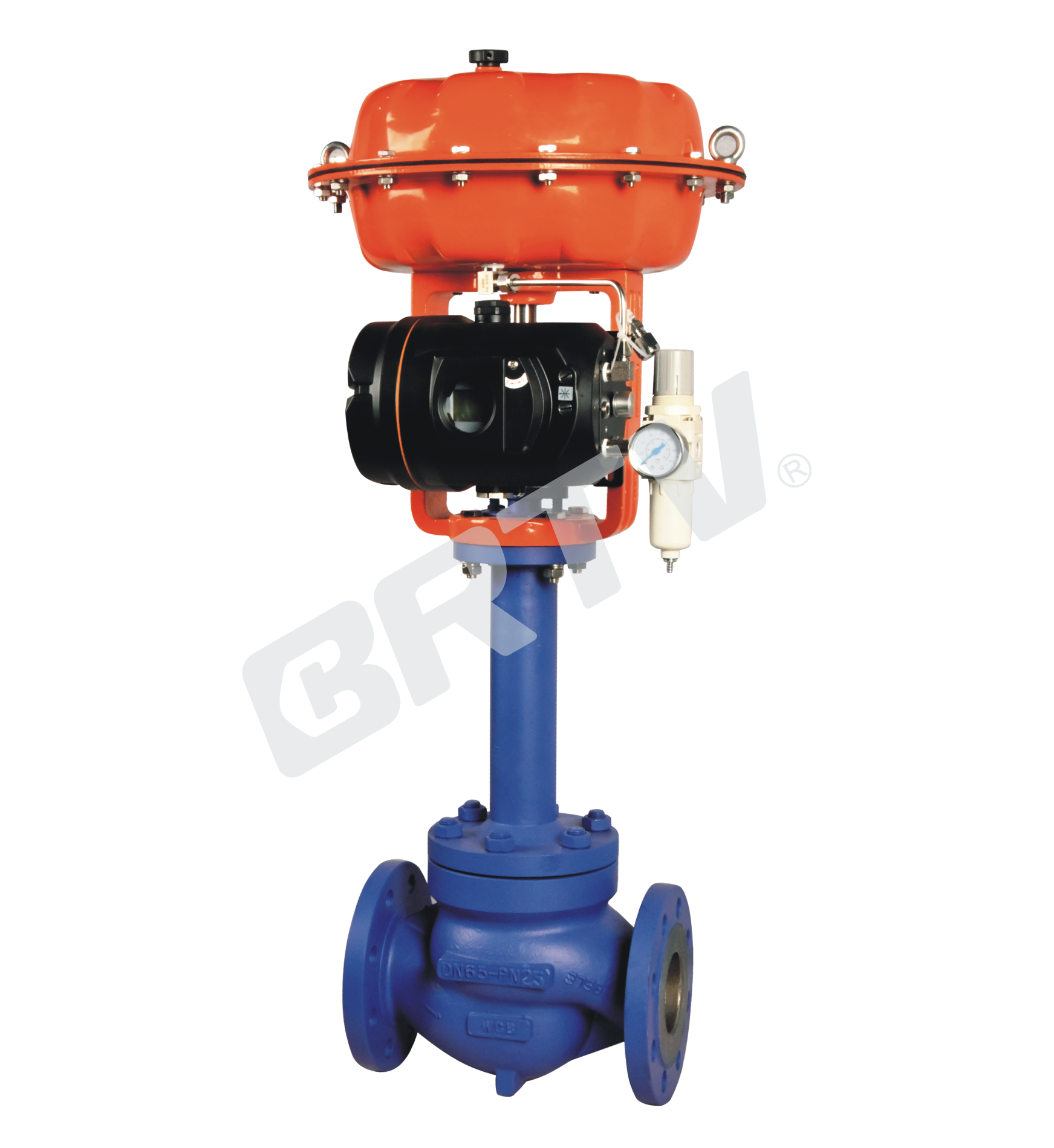
Bellows Single Seat Control Valve
bellows single seat control valve is a kind of top guide structure valve. The body structure is compact. It has S–streamline fluid channel, small pressure drop loss, large flow, wide adjustable range.
The upper bonnet adopts bellows sealing structure, which can completely eliminate the possibility of leakage of process media from the movement gap of the stem, and it is one of the remarkable characteristics of bellows sealing valve. Due to the variability and prominence of the bellows element itself with the anti–aging property, this kind of control valve completely overcomes the weakness of packing sealing valve, such as packing aging and temperature difference sensitivity. Secondly, using the bellows – packing double seal structure, it has better safety and reliability.
Therefore, it is widely used in the automatic control system of highly toxic, highly corrosive, radioactive and other rare and special media.
The valve core has large guiding area and good vibration resistance. The control valve is equipped with multi–spring diaphragm actuator or electric actuator, and has compact structure, large output torque.
Standard Specification
| Item | Specification |
|---|
| Manner | Straight Through Casting Ball Valve |
| Nominal Diameter | 16, 20, 25, 32, 40, 50, 65, 80, 100, 125, 150, 200 mm |
| Nominal Pressure | ANSI Class 125, 150, 300; JIS 10K, 16K, 20K; PN 1.6, 4.0 MPa |
| Type of Connection | Flange Type: FF, RF, RJ, TG, MFM; Weld Type: SW (40–50 mm), BW (65–200 mm) |
| The Material of Body and Bonnet | SCPH2/WCB, SCPH21/WC6, SCS13A/CF8, SCS14A/CF8M, SCS16A/CF3M; applicable within operating temperature and pressure ranges of titanium and other alloys |
| Bonnet Manner | Bellow Seal Type: −196 ~ +350°C |
| Gland Manner | Screw Fastening Type |
| Packing | V-type PTFE Packing, Graphite Packing |
| Gasket | Plain Type, Zigzag Type; Stainless Steel (SUS304, SUS316, SUS316L) and other alloys |
| Surface Coating | Blue (Epoxy). When the valve body material is stainless steel, coating is not applied |
High Precision Core Cv Value (%CF, LCF)
| Nominal Diameter | Seat Diameter | Rated Cv | Rated Stroke (mm) |
|---|
| 15 | 10 | 1.6 | 25 |
| 15 | 12 | 2.5 | 25 |
| 15 | 15 | 4 | 25 |
| 20 | 15 | 4 | 25 |
| 20 | 20 | 6.3 | 25 |
| 25 | 20 | 6.3 | 25 |
| 25 | 25 | 10 | 25 |
| 32 | 25 | 10 | 25 |
| 32 | 32 | 17 | 25 |
| 40 | 25 | 10 | 25 |
| 40 | 32 | 17 | 25 |
| 40 | 40 | 24 | 25 |
| 50 | 32 | 17 | 25 |
| 50 | 40 | 24 | 25 |
| 50 | 50 | 40 | 25 |
| 65 | 40 | 24 | 40 |
| 65 | 50 | 40 | 40 |
| 65 | 65 | 63 | 40 |
| 80 | 50 | 40 | 40 |
| 80 | 65 | 63 | 40 |
| 80 | 80 | 100 | 40 |
| 100 | 65 | 63 | 40 |
| 100 | 80 | 100 | 40 |
| 100 | 100 | 160 | 40 |
| 125 | 80 | 100 | 60 |
| 125 | 100 | 160 | 60 |
| 125 | 125 | 250 | 60 |
| 150 | 100 | 160 | 60 |
| 150 | 125 | 250 | 60 |
| 150 | 150 | 400 | 60 |
| 200 | 125 | 250 | 60 |
| 200 | 150 | 400 | 60 |
| 200 | 200 | 630 | 60 |
Actuator
| Item | Pneumatic Diaphragm Type | Cylinder Piston Type (Single Action) | Cylinder Piston Type (Double Action) | Electronic Type | Intelligent Type |
|---|
| Model | ZJHA/B | ZTCLS | ZTCL | 381 Series | ZM Series |
| Structure | Multiple Springs Type | Single Action | Double Action | — | — |
| Service | Regulation | Regulation | Regulation | Regulation | Regulation |
| Supply Gas Pressure / Supply Voltage | Supply Gas Pressure (spring range): 280(80–240) kPa / 400(80–240) kPa | Supply Gas Pressure: 400–700 kPa (300–500 kPa) | Supply Gas Pressure: 400–700 kPa (300–500 kPa) | Voltage: 220/380V 50Hz; Input Signal: 4–20 mA DC | Voltage: 220/380V 50Hz; Input Signal: 4–20 mA DC |
| Connector | Air Piping: RC1/4 | Air Piping: G1/8, G1/4, G1/2, G3/8 | Air Piping: G1/8, G1/4, G1/2, G3/8 | Wiring: PG13.5 | Wiring: PG13.5 |
| Positive Action | Adding Pressure – Valve Will Be Closed | Adding Pressure – Valve Will Be Closed | Adding Pressure – Valve Will Be Closed | Inputting the Signal – Valve Will Be Closed | Inputting the Signal – Valve Will Be Closed |
| Negative Action | Adding Pressure – Valve Will Be Opened | Adding Pressure – Valve Will Be Opened | Adding Pressure – Valve Will Be Opened | Inputting the Signal – Valve Will Be Opened | Inputting the Signal – Valve Will Be Opened |
| Hysteresis | ≤3% FS (with positioner) / ≤3% FS (no positioner) | ≤3% FS (with positioner) / ≤3% FS (no positioner) | ≤3% FS (with positioner) / ≤3% FS (no positioner) | ≤ ±1% FS | ≤ ±1% FS |
| Limit of Intrinsic Error | ≤ ±3% FS (with positioner) / ≤ ±11% FS (no positioner) | ≤ ±3% FS (with positioner) / ≤ ±11% FS (no positioner) | ≤ ±3% FS (with positioner) / ≤ ±11% FS (no positioner) | ≤ ±1% FS | ≤ ±1% FS |
| Ambient Temperature | Standard: −30 ~ +70°C; High Temperature Type: 0 ~ +100°C; Low Temperature Type: −40 ~ +40°C | Standard: −20 ~ +60°C; High Temperature Type: 0 ~ +100°C; Low Temperature Type: −50 ~ +60°C | Standard: −20 ~ +60°C; High Temperature Type: 0 ~ +100°C; Low Temperature Type: −50 ~ +60°C | −20 ~ +70°C | −25 ~ +70°C |
| Painting Color | Blue Scale 10B5/10 | Blue Scale 10B5/10 | Blue Scale 10B5/10 | — | — |
| Accessory | Positioner / Air Filtration / Pressure Reducing Valve / Transmitter / Handwheel | Positioner / Air Filtration / Pressure Reducing Valve / Transmitter / Handwheel | Positioner / Air Filtration / Pressure Reducing Valve / Transmitter / Handwheel | Integrated Type | Integrated Type |
Model Selection Parameter Table
Rated Flow Cv Value
| Seat Diameter (mm) | 10 | 12 | 15 | 20 | 25 | 32 | 40 | 50 | 65 | 80 | 100 | 125 | 150 | 200 |
|---|
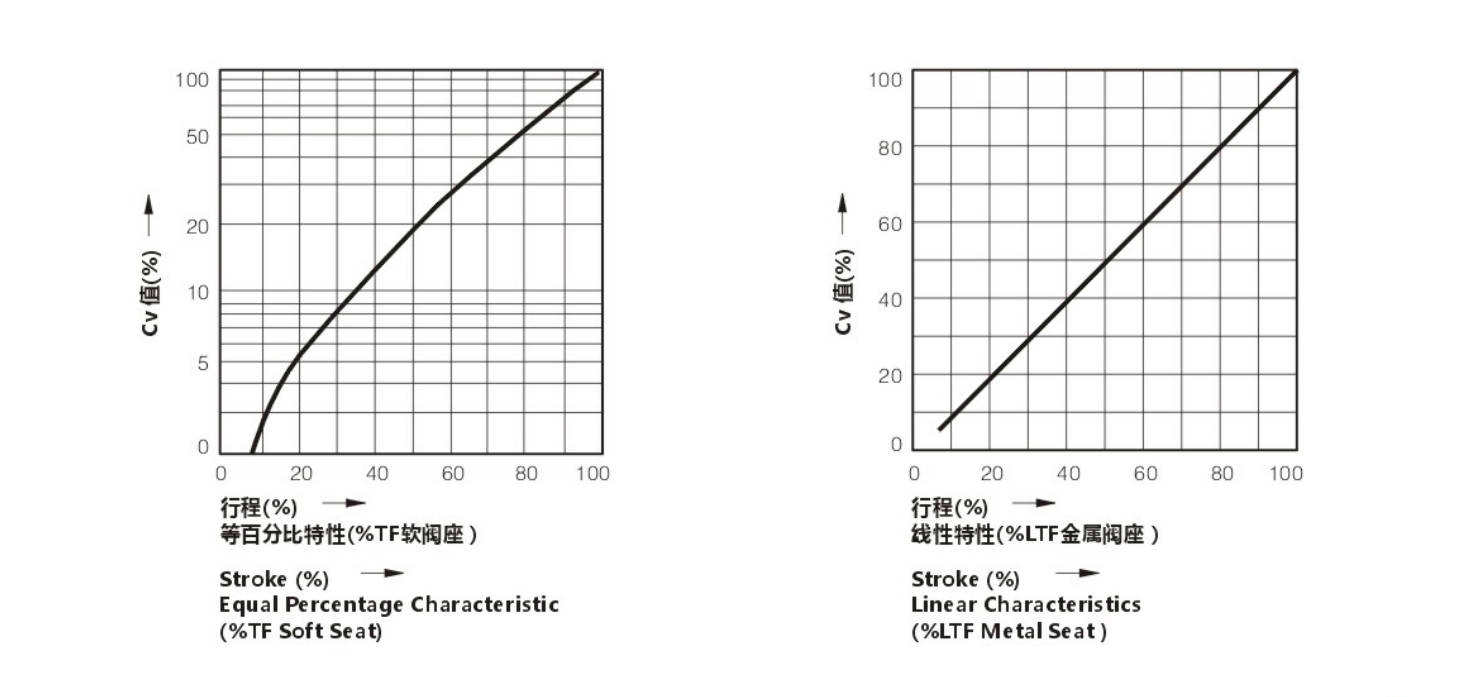
| Equal Percentage | 1.6 | 2.5 | 4 | 6.3 | 10 | 17 | 24 | 40 | 63 | 100 | 160 | 250 | 400 | 630 |
| Straight | 1.8 | 2.8 | 4.4 | 6.9 | 11 | 17.6 | 27.5 | 44 | 69 | 110 | 176 | 275 | 440 | 690 |
Optional Coefficient of Flow Cv
(★ standard type • recommend type ○ customized type)
| Nominal Diameter | Stroke | 10 | 12 | 15 | 20 | 25 | 32 | 40 | 50 | 65 | 80 | 100 | 125 | 150 | 200 |
|---|
| DN20 | 16 mm | • | • | • | ★ | | | | | | | | | | |
| DN25 | 16 mm | • | • | • | • | ★ | | | | | | | | | |
| DN32 | 25 mm | ○ | ○ | ○ | ○ | ○ | ★ | | | | | | | | |
| DN40 | 25 mm | | ○ | ○ | ○ | ○ | • | ★ | | | | | | | |
| DN50 | 25 mm | | | ○ | ○ | ○ | • | • | ★ | | | | | | |
| DN65 | 40 mm | | | | | | ○ | ○ | ○ | ★ | | | | | |
| DN80 | 40 mm | | | | | | ○ | ○ | ○ | • | ★ | | | | |
| DN100 | 40 mm | | | | | | ○ | ○ | ○ | • | • | ★ | | | |
| DN125 | 60 mm | | | | | | | | | ○ | ○ | ○ | ★ | | |
| DN150 | 60 mm | | | | | | | | | ○ | ○ | • | ○ | ★ | |
| DN200 | 60 mm | | | | | | | | | ○ | ○ | • | • | ○ | ★ |
Pneumatic Actuator Diaphragm Active Area Ae (cm²)
| Model | Active Area |
|---|
| ZHA/B-22 | 350 |
| ZHA/B-23 | 350 |
| ZHA/B-34 | 560 |
| ZHA/B-45 | 900 |
Allowable Pressure Differential of Metal Seal (MPa)
| Range of Spring | 10 | 12 | 15 | 20 | 25 | 32 | 40 | 50 | 65 | 80 | 100 | 125 | 150 | 200 |
|---|
| 20–100 kPa | 4.46 | 3.09 | 1.98 | 1.16 | 0.70 | 0.44 | 0.28 | 0.18 | 0.17 | 0.11 | 0.07 | 0.07 | 0.05 | 0.03 |
| 40–200 kPa | 6.4 | 6.4 | 5.94 | 3.34 | 2.14 | 1.31 | 0.84 | 0.53 | 0.51 | 0.33 | 0.21 | 0.22 | 0.15 | 0.09 |
| 80–240 kPa | 6.4 | 6.4 | 6.4 | 6.4 | 4.99 | 3.05 | 1.95 | 1.25 | 1.18 | 0.78 | 0.50 | 0.51 | 0.36 | 0.21 |
| Range of Spring | 10 | 12 | 15 | 20 | 25 | 32 | 40 | 50 | 65 | 80 | 100 | 125 | 150 | 200 |
|---|
| 20–100 kPa | 6.4 | 6.19 | 3.96 | 2.23 | 2.14 | 0.87 | 0.56 | 0.35 | 0.34 | 0.22 | 0.14 | 0.15 | 0.10 | 0.06 |
| 40–200 kPa | 6.4 | 6.4 | 6.4 | 6.4 | 6.4 | 5.86 | 3.64 | 2.30 | 2.21 | 1.43 | 0.91 | 0.95 | 0.66 | 0.37 |
| 80–240 kPa | 6.4 | 6.4 | 6.4 | 6.4 | 6.4 | 6.4 | 5.04 | 3.18 | 3.06 | 1.98 | 1.26 | 1.32 | 0.92 | 0.52 |
High Precision Flow Characteristic of Valve
The Size of Control Valve and Hole Shrinkage Internals&trip; Rated Cv.
| Valve Size (inch/mm) | Rated Stroke (mm) | Cv | Characteristic | 10% | 30% | 50% | 70% | 100% |
|---|
| 3/4 (20) | 16 | 1.6 | Equal % | 0.09 | 0.17 | 0.34 | 0.95 | 1.6 |
| 3/4 (20) | 16 | 1.6 | Straight | 0.27 | 0.68 | 1.09 | 1.49 | 1.8 |
| 3/4 (20) | 16 | 2.5 | Equal % | 0.14 | 0.27 | 0.53 | 1.48 | 2.5 |
| 3/4 (20) | 16 | 2.5 | Straight | 0.42 | 1.06 | 1.69 | 2.32 | 2.8 |
| 3/4 (20) | 16 | 4 | Equal % | 0.22 | 0.43 | 0.85 | 2.37 | 4 |
| 3/4 (20) | 16 | 4 | Straight | 0.67 | 1.66 | 2.65 | 3.65 | 4.4 |
| 1 (25) | 16 | 4 | Equal % | 0.22 | 0.43 | 0.85 | 2.37 | 4 |
| 1 (25) | 16 | 4 | Straight | 0.67 | 1.66 | 2.65 | 3.65 | 4.4 |
| 1 (25) | 16 | 6.3 | Equal % | 0.34 | 0.68 | 1.35 | 3.74 | 6.3 |
| 1 (25) | 16 | 6.3 | Straight | 1.05 | 2.60 | 4.16 | 5.72 | 6.9 |
| 1 1/4 (32) | 25 | 6.3 | Equal % | 0.34 | 0.68 | 1.35 | 3.74 | 6.3 |
| 1 1/4 (32) | 25 | 6.3 | Straight | 1.05 | 2.60 | 4.16 | 5.72 | 6.9 |
| 1 1/4 (32) | 25 | 10 | Equal % | 0.55 | 1.08 | 2.14 | 5.93 | 10 |
| 1 1/4 (32) | 25 | 10 | Straight | 1.67 | 4.15 | 6.64 | 9.11 | 11 |
| 1 1/2 (40) | 25 | 10 | Equal % | 0.55 | 1.08 | 2.14 | 5.93 | 10 |
| 1 1/2 (40) | 25 | 10 | Straight | 1.67 | 4.15 | 6.64 | 9.11 | 11 |
| 1 1/2 (40) | 25 | 16 | Equal % | 0.87 | 1.73 | 3.42 | 9.49 | 16 |
| 1 1/2 (40) | 25 | 16 | Straight | 2.67 | 6.63 | 10.62 | 14.58 | 17.6 |
| 2 (50) | 25 | 16 | Equal % | 0.87 | 1.73 | 3.42 | 9.49 | 16 |
| 2 (50) | 25 | 16 | Straight | 2.67 | 6.63 | 10.62 | 14.58 | 17.6 |
| 2 (50) | 25 | 25 | Equal % | 1.36 | 2.72 | 5.35 | 14.82 | 25 |
| 2 (50) | 25 | 25 | Straight | 4.17 | 10.37 | 16.59 | 22.79 | 27.5 |
| 2 1/2 (65) | 40 | 25 | Equal % | 1.36 | 2.72 | 5.35 | 14.82 | 25 |
| 2 1/2 (65) | 40 | 25 | Straight | 4.17 | 10.37 | 16.59 | 22.79 | 27.5 |
| 2 1/2 (65) | 40 | 40 | Equal % | 2.18 | 4.32 | 8.54 | 23.71 | 40 |
| 2 1/2 (65) | 40 | 40 | Straight | 6.67 | 16.58 | 26.56 | 36.46 | 44 |
| 3 (80) | 40 | 40 | Equal % | 2.18 | 4.32 | 8.54 | 23.71 | 40 |
| 3 (80) | 40 | 40 | Straight | 6.67 | 16.58 | 26.56 | 36.46 | 44 |
| 3 (80) | 40 | 63 | Equal % | 3.34 | 6.81 | 13.45 | 37.35 | 63 |
| 3 (80) | 40 | 63 | Straight | 10.47 | 26.01 | 41.63 | 57.17 | 69 |
| 4 (100) | 40 | 63 | Equal % | 3.34 | 6.81 | 13.45 | 37.35 | 63 |
| 4 (100) | 40 | 63 | Straight | 10.47 | 26.01 | 41.63 | 57.17 | 69 |
| 4 (100) | 40 | 100 | Equal % | 5.45 | 10.81 | 21.36 | 59.28 | 100 |
| 4 (100) | 40 | 100 | Straight | 16.69 | 41.46 | 66.37 | 91.14 | 110 |
| 5 (125) | 60 | 100 | Equal % | 13.62 | 10.81 | 21.36 | 59.28 | 100 |
| 5 (125) | 60 | 100 | Straight | 16.69 | 41.46 | 66.37 | 91.14 | 110 |
| 5 (125) | 60 | 160 | Equal % | 21.80 | 17.29 | 34.17 | 94.85 | 160 |
| 5 (125) | 60 | 160 | Straight | 26.70 | 66.34 | 106.2 | 145.8 | 176 |
| 6 (150) | 60 | 250 | Equal % | 13.62 | 27.06 | 53.40 | 148.2 | 250 |
| 6 (150) | 60 | 250 | Straight | 41.72 | 103.7 | 165.9 | 227.9 | 275 |
| 6 (150) | 60 | 400 | Equal % | 21.80 | 43.23 | 85.42 | 237.1 | 400 |
| 6 (150) | 60 | 400 | Straight | 66.75 | 165.85 | 265.5 | 364.6 | 440 |
| 8 (200) | 60 | 250 | Equal % | 13.62 | 27.06 | 53.40 | 148.2 | 250 |
| 8 (200) | 60 | 250 | Straight | 71.72 | 103.7 | 165.9 | 227.9 | 275 |
| 8 (200) | 60 | 400 | Equal % | 21.80 | 43.23 | 85.42 | 237.1 | 400 |
| 8 (200) | 60 | 400 | Straight | 66.75 | 165.85 | 265.5 | 364.6 | 440 |
The Material of Valve and Components, Range of Using Temperature · Allowable Leakage of Seat
Body Material: Carbon Steel
| Component | Specification | SCPH2 / A216–WCB | SCPH21 / A217–WC6 | SCPL1 / A352–LCB |
|---|
| Core | Material | SUS304/316 | SUS304/316 | SUS304/316 |
| Core | Treatment | – | R.TFE | SS/SF |
| Seat | Material | SUS304/316 | SUS304/316 | SUS304/316 |
| Seat | Treatment | – | – | SS/SF |
| Guide Sleeve | Material | SUS420 | SUS420 | SUS420 |
| Guide Sleeve | Treatment | HT | HT | HT |
| Gasket | Material | SUS316L | SUS316L | SUS316L |
| Allowable Leakage of Seat | ANSI | Class IV | Class VI | Class IV |
| Allowable Leakage of Seat | Rated CvX | 0.01% | Non-leakage | 0.01% |
| Operating Temperature (°C) | SCPH2 / WCB Body | -17 ~ +350 | -17 ~ +230 | -17 ~ +350 |
| Operating Temperature (°C) | SCPH21 / WC6 Body | -17 ~ +350 | -17 ~ +230 | -17 ~ +350 |
| Operating Temperature (°C) | SCPL1 / LCB Body | -45 ~ +350 | -45 ~ +230 | -45 ~ +350 |
Body Material: Stainless Steel
| Component | Specification | SCS13A / CF8 | SCS14A / CF8M | SCS16A / CF3M |
|---|
| Core | Material | SUS304/316/316L | SUS304/316 | SUS304/316/316L |
| Core | Treatment | – | R.TFE | SS/SF |
| Seat | Material | SUS304/316/316L | SUS304/316/316L | SUS304/316/316L |
| Seat | Treatment | – | – | SS/SF |
| Guide Sleeve | Material | SUS304/316/316L | SUS304/316/316L | SUS304/316/316L |
| Guide Sleeve | Treatment | – | R.TFE | ST |
| Gasket | Material | SUS316L | SUS316L | SUS316L |
| Allowable Leakage of Seat | ANSI | Class IV | Class VI | Class IV |
| Allowable Leakage of Seat | Rated CvX | 0.01% | Non-leakage | 0.01% |
| Operating Temperature (°C) | – | -196 ~ +350 | -45 ~ +350 | -196 ~ +350 |
Allowable Differential Pressure
Multi-spring Diaphragm Actuator
| Actuator Specification | Air Pressure (kPa) | Spring Range (kPa) | 3/4 (20) | 1 (25) | 1 1/4 (32) | 1 1/2 (40) | 2 (50) | 2 1/2 (65) | 3 (80) | 4 (100) | 5 (125) | 6 (150) | 8 (200) |
|---|
| ZJHA/B-22 | 140 | 20~100 | 1.17 | 0.75 | – | – | – | – | – | – | – | – | – |
| ZJHA/B-22 | 240 | 40~200 | 2.73 | 1.75 | – | – | – | – | – | – | – | – | – |
| ZJHA/B-22 | 300 | 80~240 | 5.85 | 3.75 | – | – | – | – | – | – | – | – | – |
| ZJHA/B-23 | 140 | 20~100 | 1.64 | 1.05 | 0.63 | 0.40 | 0.26 | – | – | – | – | – | – |
| ZJHA/B-23 | 240 | 40~200 | 3.82 | 2.45 | 1.49 | 0.96 | 0.61 | – | – | – | – | – | – |
| ZJHA/B-23 | 300 | 80~240 | 8.19 | 5.24 | 3.19 | 2.05 | 1.31 | – | – | – | – | – | – |
| ZJHA/B-34 | 140 | 20~100 | – | – | 1.02 | 0.66 | 0.42 | 0.24 | 0.16 | 0.10 | – | – | – |
| ZJHA/B-34 | 240 | 40~200 | – | – | 2.38 | 1.53 | 0.98 | 0.58 | 0.38 | 0.24 | – | – | – |
| ZJHA/B-34 | 300 | 80~240 | – | – | 5.12 | 3.28 | 2.10 | 1.24 | 0.82 | 0.52 | – | – | – |
| ZJHA/B-45 | 140 | 20~100 | – | – | – | – | – | 0.40 | 0.26 | 0.17 | 0.11 | 0.07 | 0.02 |
| ZJHA/B-45 | 240 | 40~200 | – | – | – | – | – | 0.93 | 0.61 | 0.39 | 0.25 | 0.17 | 0.07 |
| ZJHA/B-45 | 300 | 80~240 | – | – | – | – | – | 1.98 | 1.32 | 0.84 | 0.54 | 0.37 | 0.16 |
381L Series of Electronic Actuator
| Model / Specification | Voltage Rating | 3/4 (20) | 1 (25) | 1 1/4 (32) | 1 1/2 (40) | 2 (50) | 2 1/2 (65) | 3 (80) | 4 (100) | 5 (125) | 6 (150) | 8 (200) |
|---|
| 381LSA-08 | 110V / 220V / 380V | 2.38 | 1.52 | 0.93 | 0.59 | 0.38 | – | – | – | – | – | – |
| 381LSA-08 | 110V / 220V / 380V | 1.91 | 1.22 | 0.74 | 0.47 | 0.30 | – | – | – | – | – | – |
| 381LSA-20 | 110V / 220V / 380V | 4.77 | 3.05 | 1.86 | 1.19 | 0.76 | 0.45 | – | – | – | – | – |
| 381LSA-20 | 110V / 220V / 380V | 3.82 | 2.44 | 1.49 | 0.95 | 0.61 | 0.36 | – | – | – | – | – |
| 381LSB-30 | 110V / 220V / 380V | – | – | 2.79 | 1.79 | 1.14 | 0.67 | 1.21 | 0.28 | 0.18 | 0.12 | 0.03 |
| 381LSB-30 | 110V / 220V / 380V | – | – | 2.23 | 1.43 | 0.91 | 0.54 | 0.96 | 0.22 | 0.14 | 0.10 | 0.02 |
| 381LSB-50 | 110V / 220V / 380V | – | – | 4.66 | 2.98 | 1.91 | 1.13 | 1.51 | 0.47 | 0.30 | 0.21 | 0.08 |
| 381LSB-50 | 110V / 220V / 380V | – | – | 3.73 | 2.38 | 1.52 | 0.90 | 1.20 | 0.38 | 0.24 | 0.16 | 0.06 |
| 381LSC-65 | 110V / 220V / 380V | – | – | – | – | – | 1.35 | 2.34 | 0.57 | 0.36 | 0.25 | 0.11 |
| 381LSC-65 | 110V / 220V / 380V | – | – | – | – | – | 1.08 | 1.87 | 0.45 | 0.29 | 0.20 | 0.08 |
| 381LSC-99 | 110V / 220V / 380V | – | – | – | – | – | 2.26 | 2.92 | 0.95 | 0.61 | 0.42 | 0.20 |
| 381LSC-99 | 110V / 220V / 380V | – | – | – | – | – | 1.80 | 2.33 | 0.76 | 0.48 | 0.33 | 0.15 |
| 381LSC-160 | 110V / 220V / 380V | – | – | – | – | – | – | – | 0.97 | 0.67 | 0.35 | – |
| 381LSC-160 | 110V / 220V / 380V | – | – | – | – | – | – | – | 0.78 | 0.54 | 0.27 | – |
Outline Drawing
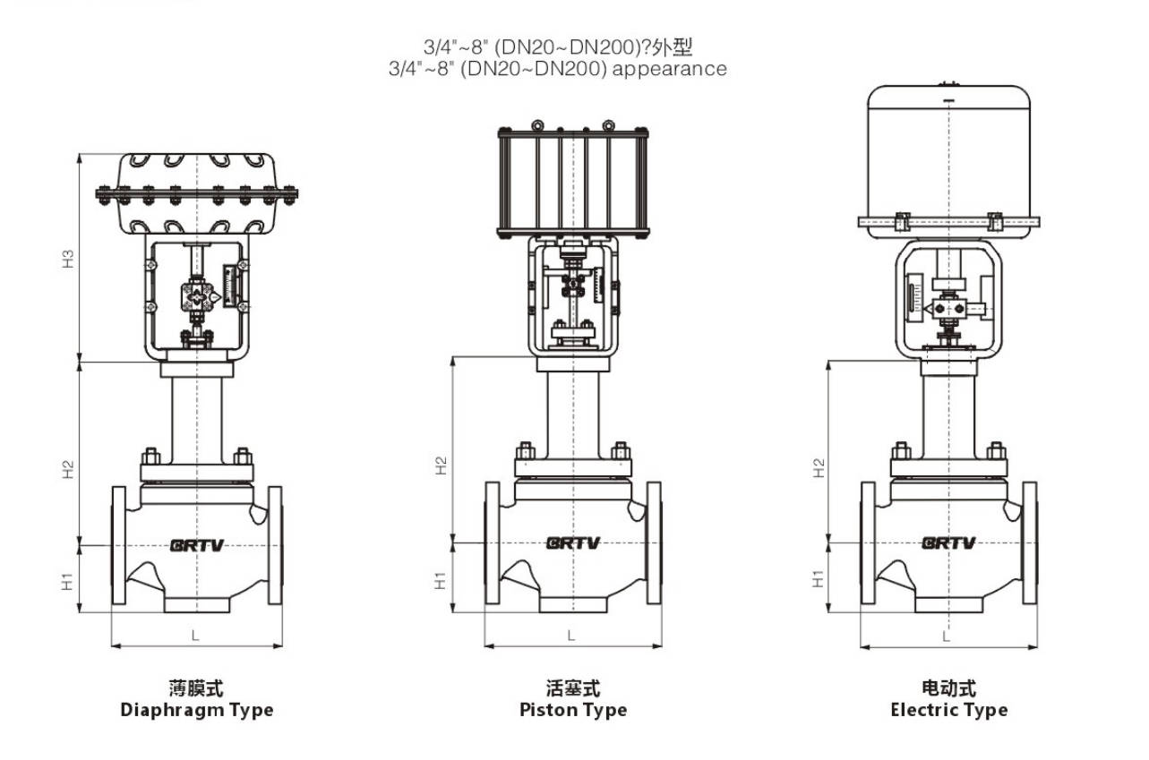
Appearance Dimension
Unit:mm
| DN (inch) | DN (mm) | ANSI150 PN16/25 (GB/T12221) | ANSI150 PN16/25 (GB/T17213.3) | ANSI300 PN40 (GB/T17213.3) | ANSI600 PN64/100 (GB/T17213.3) | H1 | H2 | H3 | Electrical Actuator | Pneumatic Actuator |
|---|
| 3/4 | 20 | 150 | 184 | 194 | 206 | 40 | 135 | 274 | 381LSA-20 | ZJHA/B-22 |
| 1 | 25 | 160 | 184 | 197 | 210 | 43 | 146 | 274 | 381LSA-20 | ZJHA/B-22 |
| 1 1/4 | 32 | 180 | 210 | 235 | 251 | 45 | 163 | 302 | 381LSB-30 | ZJHA/B-23 |
| 1 1/2 | 40 | 200 | 222 | 235 | 251 | 56 | 163 | 302 | 381LSB-30 | ZJHA/B-23 |
| 2 | 50 | 230 | 254 | 267 | 286 | 73 | 165 | 302 | 381LSB-30 | ZJHA/B-23 |
| 2 1/2 | 65 | 290 | 276 | 292 | 311 | 83 | 217 | 375 | 381LSB-50 | ZJHA/B-34 |
| 3 | 80 | 310 | 298 | 317 | 337 | 102 | 235 | 375 | 381LSB-50 | ZJHA/B-34 |
| 4 | 100 | 350 | 352 | 368 | 394 | 110 | 236 | 375 | 381LSB-50 | ZJHA/B-34 |
| 5 | 125 | 400 | 402 | 425 | 507 | 146 | 340 | 465 | 381LSC-99 | ZJHA/B-45 |
| 6 | 150 | 480 | 451 | 473 | 508 | 170 | 340 | 465 | 381LSC-99 | ZJHA/B-45 |
| 8 | 200 | 600 | 543 | 568 | 610 | 220 | 383 | 465 | 381LSC-99 | ZJHA/B-45 |
Manufacturing Process
Step 1: Order and Design
Based on the operating conditions parameters provided by the customer, such as pipe diameter, pressure grade, temperature, medium type and leakage level, the structural form, valve body material, diaphragm material and actuator configuration of the bellows single seat control valve are confirmed. The drawing design, BOM list and process route are completed for confirmation, providing a basis for subsequent production.
Step 2: Forging & Casting
The pressure-bearing components such as valve bodies and valve covers are usually formed by casting or forging processes, and undergo heat treatment and blank inspection according to material standards. For bellows single-seat control valves, it is particularly important to ensure the valve body flow channel dimensions, the reserved machining allowance for the sealing surfaces, and the internal quality of the material, to avoid defects such as pores, shrinkage cavities and cracks.
Step 3: Machining
The valve body, valve cover, valve seat, valve stem, and connecting parts are subjected to precise mechanical processing, including turning, boring, drilling, tapping, and sealing surface processing. The processing focus of the bellows single-seat control valve is the accuracy of the valve seat sealing surface, the coaxiality of the valve stem, and the installation fitting dimensions of the bellows, in order to ensure the adjustment accuracy and sealing performance.
Step 4: Assembly
According to the assembly process, the valve internals, bellows components, valve stem, valve core, packing, and actuator are gradually assembled, and the stroke and connection positions are adjusted. During the assembly of the bellows single-seat control valve, special attention should be paid to the protection of the welding parts of the bellows, the coordination between the valve core and the valve seat, as well as the flexibility and stability of the actuator's operation.
Step 5: Testing & Quality Assurance
After assembly is completed, conduct pressure tests, leakage tests, stroke calibration and operation tests on the product to ensure that the valve meets the design requirements. For bellows single-seat control valves, in addition to the regular shell and seal tests, special attention should be paid to checking the sealing performance of the bellows, the stability of the adjustment, and the overall valve operation response to ensure the safety and reliability of the product.
Step 6: Painting and Finishing
After the test is qualified, the outer surface of the valve will be cleaned, rust removed, primed and painted. The nameplate, labels, protective covers and packaging will also be completed. Finally, the appearance of the finished product will be inspected and the factory documents will be sorted out to ensure that the product meets the requirements for transportation and on-site installation.
Applications
The bellows single seat control valve is a high-performance control valve with a bellows sealing structure. Its core advantage lies in the ability to achieve zero leakage at the valve stem, making it indispensable for handling dangerous, valuable, or volatile media.
These valves are widely used in:
Agriculture and Irrigation
Factory Environment
Why Choose Us
Superior Quality

Our valves are manufactured using premium materials and undergo rigorous quality testing to ensure reliable performance in demanding industrial applications.
Advanced Technology

Equipped with state-of-the-art CNC machining centers and precision manufacturing equipment, we deliver valves with exceptional accuracy and consistency.
Competitive Pricing

Through optimized manufacturing processes and bulk material procurement, we offer high-quality valves at competitive prices without compromising on quality.
Expert Support

Our experienced technical team provides comprehensive support from product selection to after-sales service, ensuring optimal valve performance for your specific application.