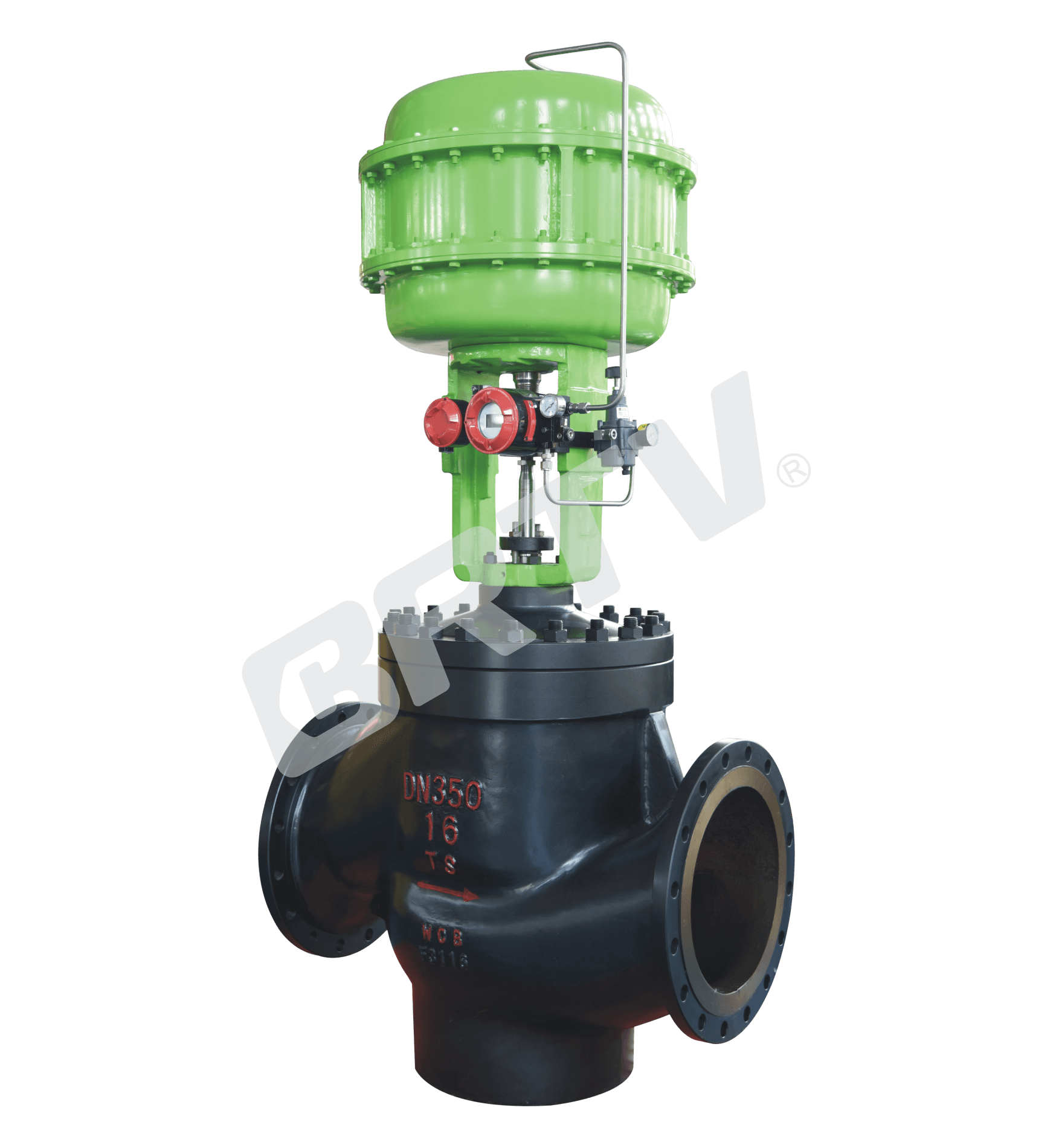
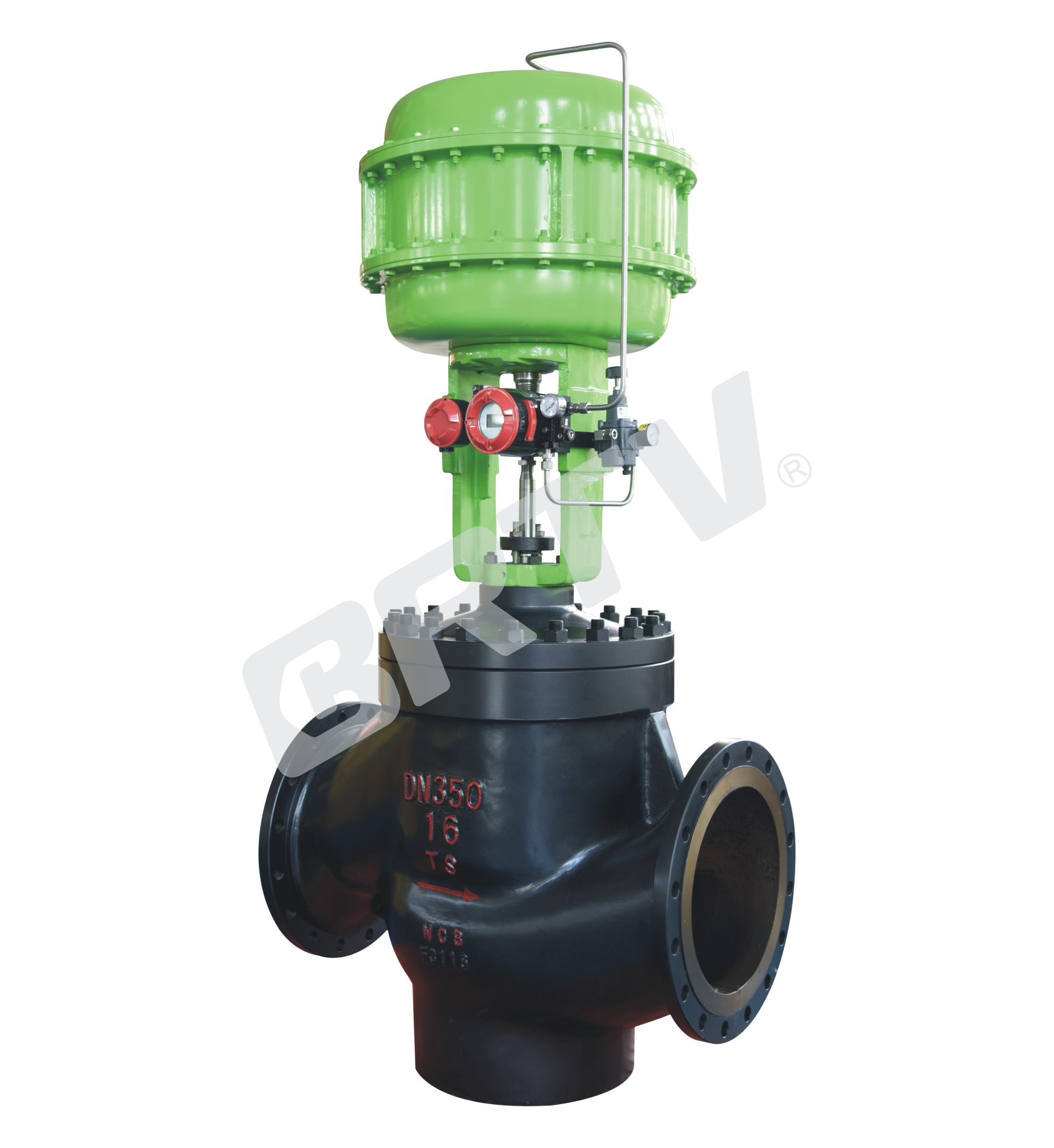
Low Noise Cage Type Control Valve
low noise cage type control valve is mainly designed to reduce the noise of compressible fluid, and to adapt the gas throttle diffusion and expansion. The sleeve is provided with many symmetrical holes to reduce the pressure drop. The fluid passage is s–streamlined. It is equipped with turning vane to improve the smooth flow of fluid around the sleeve. So that the control valve has small pressure drop loss, large flow, and small noise.
The valve core adopts pressure balance structure. The control valve is equipped with multi–spring diaphragm actuator or electric actuator, and has compact structure, large output torque.
Standard Specification
| Manner | Straight through single seat cast ball valve |
|---|
| Nominal Diameter | 40, 50, 65, 80, 100, 125, 150, 200, 250, 300, 350, 400 mm |
| Nominal Pressure | ANSI Class 125, 150, 300, 600; JIS 10K, 20K, 30K, 40K; PN 1.6, 4.0, 6.4 MPa |
| Type of Connection | Flange type: FF, RF, RJ, TG, MFM; Weld type: SW (40–50 mm), BW (65–400 mm) |
| The Material of Body and Bonnet | SCPH2/WCB, SCPH21/WC6, SCS13A/CF8, SCS14A/CF8M, SCS16A/CF3M; also suitable for titanium and other alloy materials within corresponding temperature and pressure ranges |
| Bonnet Manner | Normal temperature (P): −17 ~ +230°C; Elongation type I (EI): −45 ~ −17°C and +230 ~ +566°C; Elongation type II (EII): −100 ~ −45°C |
| Gland Manner | Screw Fastening Type |
| Packing | V-type PTFE Packing; Graphite Packing |
| Gasket | Plain type; Zigzag type; Stainless steel (SUS304, SUS316, SUS316L) and other alloys |
| Surface Coating | Blue (epoxy). When the valve body material is stainless steel, coating is not applied |
flange Standard:JIS B2201–1984, JB/T79.1–94 (PN1.6MPa), JB/T79.2–94 (PN4.0, 6.4MPa), ANSI B16.5–2009, HG20592–2009, HG20615–2009.
Cv Valve and Stroke
Rated Cv and Flow Characteristic
| Nominal Diameter | Seat Diameter | Rated Cv | Flow Characteristic (LC) | Flow Characteristic (%C) |
|---|
| 40 | 25 | 11 | △ | △ |
| 40 | 32 | 17 | △ | |
| 40 | 40 | 24 | △ | △ |
| 50 | 32 | 17 | △ | △ |
| 50 | 40 | 24 | △ | |
| 50 | 50 | 44 | △ | |
| 65 | 40 | 24 | △ | △ |
| 65 | 50 | 44 | △ | |
| 65 | 65 | 68 | △ | △ |
| 80 | 50 | 44 | △ | △ |
| 80 | 65 | 68 | △ | |
| 80 | 80 | 99 | △ | |
| 100 | 65 | 68 | △ | △ |
| 100 | 80 | 99 | △ | |
| 100 | 100 | 120 | △ | |
| 125 | 80 | 99 | △ | △ |
| 125 | 100 | 120 | △ | |
| 125 | 125 | 175 | △ | |
Rated Stroke
| Nominal Diameter Range | Rated Stroke (mm) |
|---|
| 40 – 65 | 25 |
| 80 – 100 | 40 |
| 125 | 60 |
Large Size Valves
| Nominal Diameter | Seat Diameter | Rated Cv | Flow Characteristic (LC) | Flow Characteristic (%C) |
|---|
| 150 | 100 | 120 | △ | △ |
| 150 | 125 | 175 | △ | |
| 150 | 150 | 330 | △ | |
| 200 | 125 | 175 | △ | △ |
| 200 | 150 | 330 | △ | |
| 200 | 200 | 580 | △ | |
| 250 | 150 | 330 | △ | △ |
| 250 | 200 | 580 | △ | |
| 250 | 250 | 760 | △ | |
| 300 | 200 | 580 | △ | △ |
| 300 | 250 | 760 | △ | |
| 300 | 300 | 1090 | △ | |
| 350 | 250 | 760 | △ | △ |
| 350 | 300 | 1090 | △ | |
| 350 | 350 | 1610 | △ | |
| 400 | 300 | 1090 | △ | △ |
| 400 | 350 | 1610 | △ | |
| 400 | 400 | 2100 | △ | |
Rated Stroke
| Nominal Diameter Range | Rated Stroke (mm) |
|---|
| 150 – 200 | 60 |
| 250 – 300 | 100 |
| 350 – 400 | 120 |
Note: Symbol Means The Range Of Valve Specifications
Actuator
| Item | Pneumatic Diaphragm Type | Cylinder Piston Type | Electronic Type | Intelligent Type |
|---|
| Model | ZJHA/B | ZTCLS / ZTCL | 381 Series | ZM Series |
| Structure | Multiple Springs Type | Double Action | — | — |
| Service | Regulation | Regulation | Regulation | Regulation |
| Supply Gas Pressure / Supply Voltage | Supply Gas Pressure (spring range): 280(80–240) kPa / 400(80–240) kPa | Supply Gas Pressure: 300–500 kPa | Voltage: 220/380V 50Hz; Input Signal: 4–20mA DC | Voltage: 220/380V 50Hz; Input Signal: 4–20mA DC |
| Connector | Air Piping: RC1/4 | Air Piping: G1/8, G1/4, G1/2, G3/8 | Wiring: PG13.5 | Wiring: PG13.5 |
| Positive Action | Adding Pressure – Valve Will Be Closed | Adding Pressure – Valve Will Be Closed | Inputting Signal – Valve Will Be Closed | Inputting Signal – Valve Will Be Closed |
| Negative Action | Adding Pressure – Valve Will Be Opened | Adding Pressure – Valve Will Be Opened | Inputting Signal – Valve Will Be Opened | Inputting Signal – Valve Will Be Opened |
| Hysteresis | ≤1% FS (with positioner); ≤3% FS (no positioner) | ≤1% FS (with positioner); ≤3% FS (no positioner) | =1% FS | =1% FS |
| Limit of Intrinsic Error | ≤1% FS (with positioner); ≤5% FS (no positioner) | ≤1% FS (with positioner); ≤5% FS (no positioner) | =1% FS | =1% FS |
| Ambient Temperature | Standard: −30~+70°C; High Temp: 0~+100°C; Low Temp: −40~+40°C | Standard: −20~+60°C; High Temp: 0~+100°C; Low Temp: −50~+60°C | −20~+70°C | −25~+70°C |
| Painting Color | Blue Scale 10B5/10 | Blue Scale 10B5/10 | BI | — |
| Accessory | Positioner / Air Filtration / Pressure Reducing Valve / Transmitter / Handwheel | Positioner / Air Filtration / Pressure Reducing Valve / Transmitter / Handwheel | Integrated Type | Integrated Type |
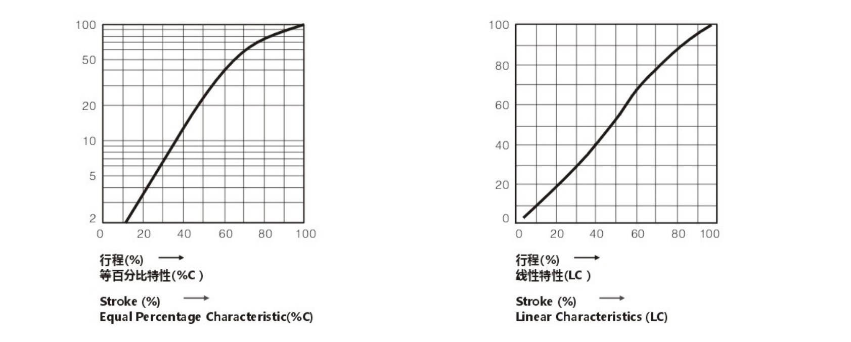
Typical Flow Characteristic of Valve
Model Selection Parameter Table
Rated Flow Cv Value
| Seat Diameter (mm) | 32 | 40 | 50 | 65 | 80 | 100 | 125 | 150 | 200 | 250 | 300 | 350 | 400 |
|---|
| Equal Percentage | 17 | 24 | 40 | 63 | 100 | 160 | 250 | 400 | 630 | 1000 | 1400 | 1700 | 1800 |
| Straight | 17.6 | 27.5 | 44 | 69 | 110 | 176 | 275 | 440 | 690 | 1100 | 1500 | 2050 | 2730 |
Optional Coefficient of Flow Cv
(★ standard type • recommend type ○ customized type)
| Nominal Diameter | Stroke | 32 | 40 | 50 | 65 | 80 | 100 | 125 | 150 | 200 | 250 | 300 | 350 | 400 |
|---|
| DN32 | 25 mm | ★ | | | | | | | | | | | | |
| DN40 | 25 mm | • | ★ | | | | | | | | | | | |
| DN50 | 25 mm | • | • | ★ | | | | | | | | | | |
| DN65 | 40 mm | ○ | ○ | ○ | ★ | | | | | | | | | |
| DN80 | 40 mm | ○ | ○ | ○ | • | ★ | | | | | | | | |
| DN100 | 40 mm | ○ | ○ | ○ | • | • | ★ | | | | | | | |
| DN125 | 60 mm | | | | ○ | ○ | ○ | ★ | | | | | | |
| DN150 | 60 mm | | | | | ○ | ○ | • | ★ | | | | | |
| DN200 | 60 mm | | | | | ○ | ○ | • | • | ★ | | | | |
| DN250 | 100 mm | | | | | | | ○ | • | • | ★ | | | |
| DN300 | 100 mm | | | | | | | | ○ | • | • | ★ | | |
| DN350 | 120 mm | | | | | | | | | | | • | ★ | |
| DN400 | 120 mm | | | | | | | | | | | | • | ★ |
Pneumatic Actuator Diaphragm Active Area Ae (cm²)
| Model | Active Area |
|---|
| ZHA/B-23 | 350 |
| ZHA/B-34 | 560 |
| ZHA/B-45 | 900 |
| ZHA/B-56 | 1600 |
Allowable Pressure Differential of Metal Seal (MPa)
| Range of Spring | 32 | 40 | 50 | 65 | 80 | 100 | 125 | 150 | 200 | 250 | 300 | 350 | 400 |
|---|
| 20–100 kPa | 2.25 | 2.25 | 1.95 | 2.36 | 2.04 | 1.67 | 1.41 | 1.41 | 1.14 | 0.65 | 0.55 | 0.50 | 0.48 |
| 40–200 kPa | 6.4 | 6.4 | 6.4 | 6.4 | 6.4 | 6.4 | 6.4 | 6.4 | 6.4 | 1.55 | 1.40 | 1.30 | 1.25 |
| 80–240 kPa | 6.4 | 6.4 | 6.4 | 6.4 | 6.4 | 6.4 | 6.4 | 6.4 | 6.4 | 4.08 | 4.08 | 3.85 | 0.48 |
| Range of Spring | 32 | 40 | 50 | 65 | 80 | 100 | 125 | 150 | 200 | 250 | 300 | 350 | 400 |
|---|
| 20–100 kPa | 1.13 | 1.13 | 0.98 | 1.18 | 1.02 | 0.84 | 0.71 | 0.71 | 0.57 | 0.65 | 0.55 | 0.50 | 0.48 |
| 40–200 kPa | 3.38 | 3.38 | 2.93 | 3.54 | 3.06 | 2.51 | 2.12 | 2.12 | 1.71 | 1.80 | 1.55 | 1.40 | 0.48 |
| 80–240 kPa | 6.4 | 6.4 | 6.4 | 6.4 | 6.4 | 5.85 | 4.94 | 4.94 | 4.00 | 4.08 | 3.65 | 3.40 | 3.20 |
The Size of Control Valve and Hole Shrinkage Internals & Trip; Rated Cv.
Unit: MPa
| Valve Size (inch/mm) | Rated Stroke (mm) | Cv Type | 10% | 30% | 50% | 70% | 100% | 10% | 30% | 50% | 70% | 100% |
|---|
| | | Equal Percentage Characteristics | | | | | Straight Characteristics | | | | |
| 3/4 (20) | 16 | Equal % | 0.09 | 0.17 | 0.34 | 0.95 | 1.6 | 0.27 | 0.68 | 1.09 | 1.49 | 1.8 |
| 3/4 (20) | 16 | Straight | 0.14 | 0.27 | 0.53 | 1.48 | 2.5 | 0.42 | 1.06 | 1.69 | 2.32 | 2.8 |
| 3/4 (20) | 16 | Straight | 0.22 | 0.43 | 0.85 | 2.37 | 4 | 0.67 | 1.66 | 2.65 | 3.65 | 4.4 |
| 1 (25) | 16 | Equal % | 0.22 | 0.43 | 0.85 | 2.37 | 4 | 0.67 | 1.66 | 2.65 | 3.65 | 4.4 |
| 1 (25) | 16 | Straight | 0.34 | 0.68 | 1.35 | 3.74 | 6.3 | 1.05 | 2.60 | 4.16 | 5.72 | 6.9 |
| 1 1/4 (32) | 25 | Equal % | 0.34 | 0.68 | 1.35 | 3.74 | 6.3 | 1.05 | 2.60 | 4.16 | 5.72 | 6.9 |
| 1 1/4 (32) | 25 | Straight | 0.55 | 1.08 | 2.14 | 5.93 | 10 | 1.67 | 4.15 | 6.64 | 9.11 | 11 |
| 1 1/2 (40) | 25 | Equal % | 0.55 | 1.08 | 2.14 | 5.93 | 10 | 1.67 | 4.15 | 6.64 | 9.11 | 11 |
| 1 1/2 (40) | 25 | Straight | 0.87 | 1.73 | 3.42 | 9.49 | 16 | 2.67 | 6.63 | 10.62 | 14.58 | 17.6 |
| 2 (50) | 25 | Equal % | 0.87 | 1.73 | 3.42 | 9.49 | 16 | 2.67 | 6.63 | 10.62 | 14.58 | 17.6 |
| 2 (50) | 25 | Straight | 1.36 | 2.72 | 5.35 | 14.82 | 25 | 4.17 | 10.37 | 16.59 | 22.79 | 27.5 |
| 2 1/2 (65) | 40 | Equal % | 1.36 | 2.72 | 5.35 | 14.82 | 25 | 4.17 | 10.37 | 16.59 | 22.79 | 27.5 |
| 2 1/2 (65) | 40 | Straight | 2.18 | 4.32 | 8.54 | 23.71 | 40 | 6.67 | 16.58 | 26.56 | 36.46 | 44 |
| 3 (80) | 40 | Equal % | 2.18 | 4.32 | 8.54 | 23.71 | 40 | 6.67 | 16.58 | 26.56 | 36.46 | 44 |
| 3 (80) | 40 | Straight | 3.34 | 6.81 | 13.45 | 37.35 | 63 | 10.47 | 26.01 | 41.63 | 57.17 | 69 |
| 4 (100) | 40 | Equal % | 3.34 | 6.81 | 13.45 | 37.35 | 63 | 10.47 | 26.01 | 41.63 | 57.17 | 69 |
| 4 (100) | 40 | Straight | 5.45 | 10.81 | 21.36 | 59.28 | 100 | 16.69 | 41.46 | 66.37 | 91.14 | 110 |
| 5 (125) | 60 | Equal % | 13.62 | 10.81 | 21.36 | 59.28 | 100 | 16.69 | 41.46 | 66.37 | 91.14 | 110 |
| 5 (125) | 60 | Straight | 21.80 | 17.29 | 34.17 | 94.85 | 160 | 26.70 | 66.34 | 106.2 | 145.8 | 176 |
| 6 (150) | 60 | Equal % | 13.62 | 27.06 | 53.40 | 148.2 | 250 | 41.72 | 103.7 | 165.9 | 227.9 | 275 |
| 6 (150) | 60 | Straight | 21.80 | 43.23 | 85.42 | 237.1 | 400 | 66.75 | 165.85 | 265.5 | 364.6 | 440 |
| 8 (200) | 60 | Equal % | 13.62 | 27.06 | 53.40 | 148.2 | 250 | 71.72 | 103.7 | 165.9 | 227.9 | 275 |
| 8 (200) | 60 | Straight | 21.80 | 43.23 | 85.42 | 237.1 | 400 | 66.75 | 165.85 | 265.5 | 364.6 | 440 |
The Material of Valve and Components, Range of Using Temperature · Allowable Leakage of Seat
Body Material: Carbon Steel
| Category | Item | Property | Option 1 | Option 2 | Option 3 | Option 4 |
|---|
| Body Material | Body | Material | SCPH2/A216-WCB | SCPH21/A217-WC5 | SCPL1/A352-LCB | — |
| Sleeve | Sleeve | Material | SUS630 / SCS24 | SUS630 / SCS24 | SUS630 / SCS24 | SUS630 / SCS24 |
| Sleeve | Sleeve | Treatment | HT | HT | HT | HT |
| Core | Core | Material | SUS410 | SUS410 | SUS410 | SUS410 |
| Core | Core | Treatment | HT | HT | HT | HT |
| Seat | Seat | Material | SUS316 + R.TFE | PEEK | SUS630 | SUS630 |
| Seat | Seat | Treatment | – | – | HT | HT |
| Balanced Ring | Balanced Ring | Material | R.TFE | R.TFE | R.TFE | Inconel 750 |
| Balanced Ring | Balanced Ring | Treatment | SUS316 | SUS316 | SUS316 | – |
| Gasket | Gasket | Material | SUS316L | SUS316L | SUS316L | SUS316L |
| Allowable Leakage of Seat | Leakage | Class | Class V | Rated Cv × 0.0001% | Class IV | Class IV |
| Operating Temperature (°C) | SCPH2/WCB Body | Range | −17 ~ +230 | −17 ~ +270 | – | −17 ~ +425 |
| Operating Temperature (°C) | SCPH21/WC6 Body | Range | −17 ~ +230 | −17 ~ +270 | – | −17 ~ +566 |
| Operating Temperature (°C) | SCPL1/LCB Body | Range | −45 ~ +230 | −45 ~ +270 | – | −45 ~ +350 |
R.TFE : Reinforced PTFE HT : Heat Treatment ST : Surfacing Sitalai Alloy SS : Partial Surfacing Sitalai Alloys SF : All Surfacing Sitalai Alloys
Body Material: Stainless Steel
| Category | Item | Property | Option 1 | Option 2 | Option 3 | Option 4 |
|---|
| Body Material | Body | Material | SCS13A/A351-CF8 | SCS14A/A351-CF8M | SCS16A/A351-CF3M | — |
| Sleeve | Sleeve | Material | SUS304/316/316L | SUS304/316/316L | SUS304/316/316L | SUS304/316/316L |
| Sleeve | Sleeve | Treatment | – | – | – | – |
| Core | Core | Material | SUS304/316/316L | SUS304/316/316L | SUS304/316/316L | SUS304/316/316L |
| Core | Core | Treatment | – | – | ST | ST |
| Seat | Seat | Material | SUS304/316/316L + R.TFE | SUS304/316/316L + PEEK | SUS304/316/316L | SUS304/316/316L |
| Seat | Seat | Treatment | – | – | ST | ST |
| Balanced Ring | Balanced Ring | Material | R.TFE | R.TFE | R.TFE | Inconel 750 |
| Balanced Ring | Balanced Ring | Treatment | SUS316 / Hastelloy C alloys | SUS316 / Hastelloy C alloys | SUS316 / Hastelloy C alloys | – |
| Gasket | Gasket | Material | SUS316L | SUS316L | SUS316L | SUS316L |
| Allowable Leakage of Seat | Leakage | Class | Class V | Rated Cv × 0.0001% | Class IV | Class IV |
| Operating Temperature (°C) | Temperature Range | Range | −75 ~ +230 | −75 ~ +270 | −196 ~ +270 | −196 ~ +566 |
Note: the fluid temperature is under −75°C, the material of balance sealing ring: Fluoroloy G, backing ring: Elgiloy
Outline Drawing
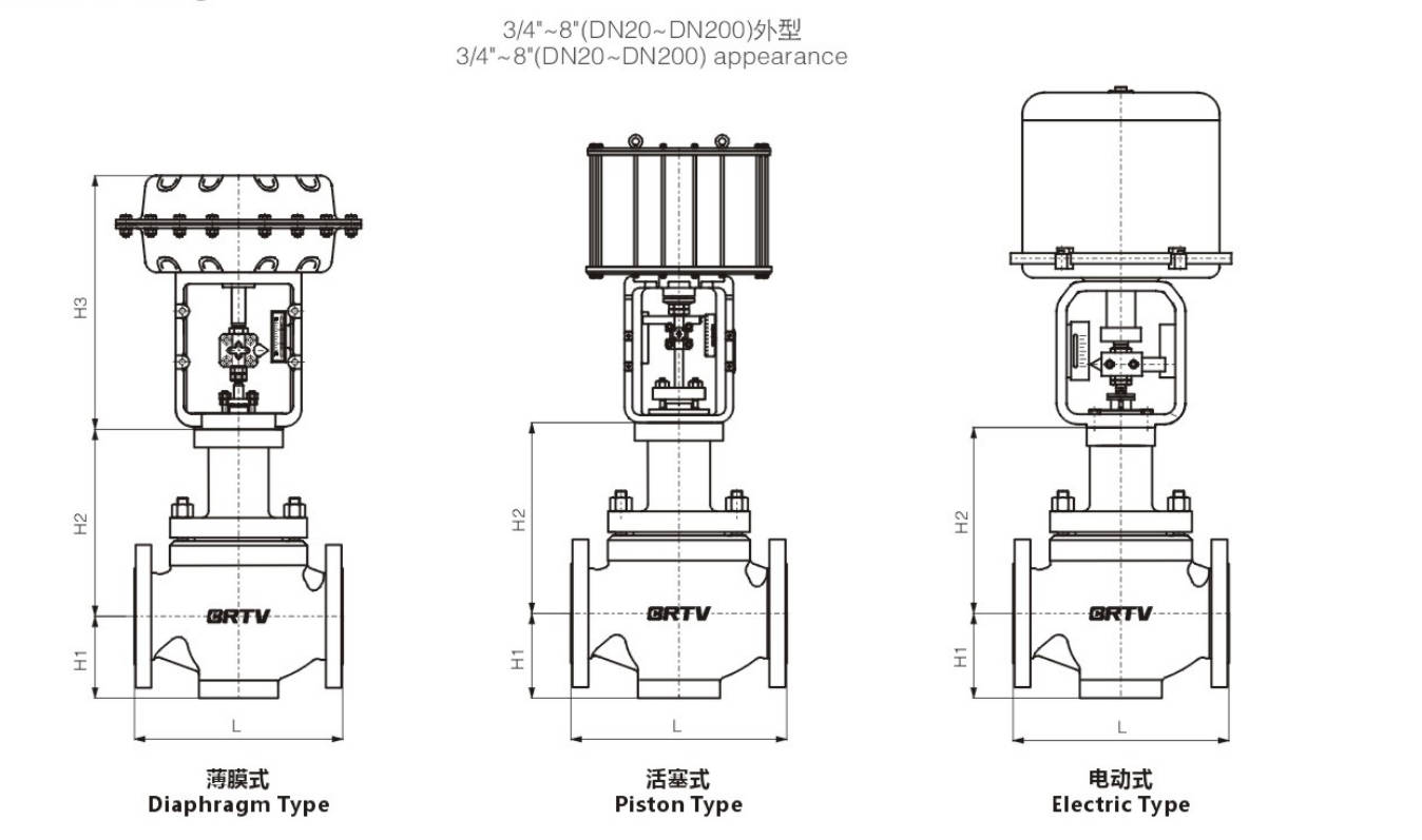
Appearance Dimension
Unit:mm
| DN (inch) | DN (mm) | L ANSI150 (GB/T12221) | L ANSI150 (GB/T17213.3) | L ANSI300 (GB/T17213.3) | L ANSI600 (GB/T17213.3) | H1 | H2 | H3 | Electrical Actuator | Pneumatic Actuator |
|---|
| 1 1/4 | 32 | 180 | 210 | 235 | 251 | 45 | 163 | 302 | 381LSB-30 | ZJHA/B 23 |
| 1 1/2 | 40 | 200 | 222 | 235 | 251 | 56 | 163 | 302 | 381LSB-30 | ZJHA/B 23 |
| 2 | 50 | 230 | 254 | 267 | 286 | 73 | 165 | 302 | 381LSB-30 | ZJHA/B 23 |
| 2 1/2 | 65 | 290 | 276 | 292 | 311 | 83 | 217 | 375 | 381LSB-50 | ZJHA/B 34 |
| 3 | 80 | 310 | 298 | 317 | 337 | 102 | 235 | 375 | 381LSB-50 | ZJHA/B 34 |
| 4 | 100 | 350 | 352 | 368 | 394 | 110 | 236 | 375 | 381LSB-50 | ZJHA/B 34 |
| 5 | 125 | 400 | 402 | 425 | 457 | 146 | 340 | 465 | 381LSC-99 | ZJHA/B 45 |
| 6 | 150 | 480 | 451 | 473 | 508 | 170 | 340 | 465 | 381LSC-99 | ZJHA/B 45 |
| 8 | 200 | 600 | 543 | 568 | 610 | 220 | 383 | 465 | 381LSC-99 | ZJHA/B 45 |
| 10 | 250 | 730 | 673 | 708 | 752 | 305 | 427 | 666 | 381LSC-160 | ZJHA/B56 |
| 12 | 300 | 850 | 737 | 775 | 819 | 345 | 435 | 666 | 381LSC-260 | ZJHA/B56 |
| 14 | 350 | 980 | 889 | 889 | 972 | 385 | 435 | 680 | 381LSC-400 | ZTCL Series |
| 16 | 400 | 1100 | 1016 | 1016 | 1108 | 420 | 454 | 680 | 381LSC-400 | ZTCL Series |
Manufacturing Process
Step 1: Order and Design
Confirm the service conditions, pressure class, size, material, leakage class, and noise reduction requirements of the low noise cage type control valve.
According to the working parameters, prepare the design drawings for valve body, cage, plug, seat ring, actuator, and trim structure.
Step 2: Forging & Casting
Select suitable raw materials for the valve body, bonnet, and internal parts according to project specifications.
The pressure-bearing parts are produced by forging or casting, followed by heat treatment and material inspection to ensure the strength and reliability required for the low noise cage type control valve.
Step 3: Machining
Carry out precision machining for valve body, bonnet, cage, plug, seat ring, stem, and flange faces.
Special attention is given to the cage holes, guiding surfaces, and sealing areas, because machining accuracy directly affects the flow control and noise reduction performance of the low noise cage type control valve.
Step 4: Assembly
After all parts pass dimensional inspection, assemble the valve trim, bonnet, gasket, stem, packing, and actuator.
During this process, the cage and plug must be fitted accurately to ensure stable regulation performance and low-noise operation of the low noise cage type control valve.
Step 5: Testing & Quality Assurance
Each low noise cage type control valve shall undergo pressure test, seat leakage test, stroke calibration, and action test.
If required by the customer, additional inspection such as NDE, PMI, material verification, and painting inspection can also be carried out to guarantee product quality.
Step 6: Painting and Finishing
After testing is completed, clean the valve surface and apply primer and finish coating according to project requirements.
Finally, complete nameplate marking, packing, and shipment preparation to ensure the low noise cage type control valve is well protected during transportation.
Applications
Low noise cage type control valves are mainly used in industrial control systems for scenarios with high pressure differences, high gas flow rates, and high noise generation (such as depressurization, pressure stabilization, air separation, and petrochemical processes), effectively reducing the pneumatic noise caused by fluid turbulence and preventing cavitation and erosion. Their application scenarios include pipeline systems that require strict noise control and stable pressure regulation.
These valves are widely used in:
Agriculture and Irrigation
Factory Environment
Why Choose Us
Superior Quality

Our valves are manufactured using premium materials and undergo rigorous quality testing to ensure reliable performance in demanding industrial applications.
Advanced Technology

Equipped with state-of-the-art CNC machining centers and precision manufacturing equipment, we deliver valves with exceptional accuracy and consistency.
Competitive Pricing

Through optimized manufacturing processes and bulk material procurement, we offer high-quality valves at competitive prices without compromising on quality.
Expert Support

Our experienced technical team provides comprehensive support from product selection to after-sales service, ensuring optimal valve performance for your specific application.