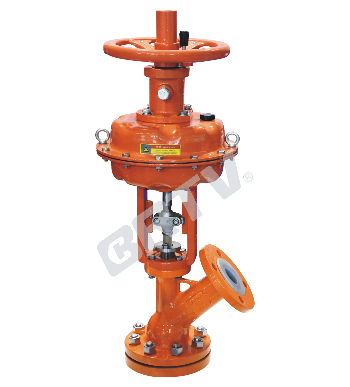
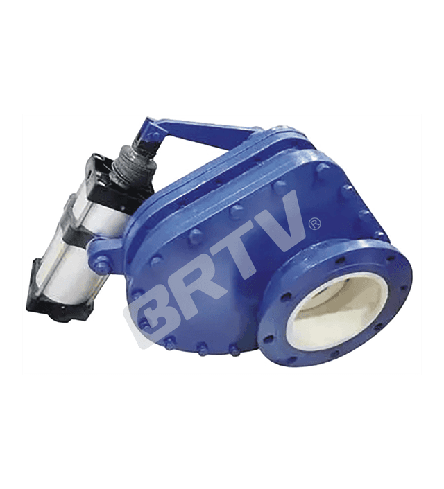
Discharge Valve
⍉ Efficient Discharge:Ensures smooth and complete material draining
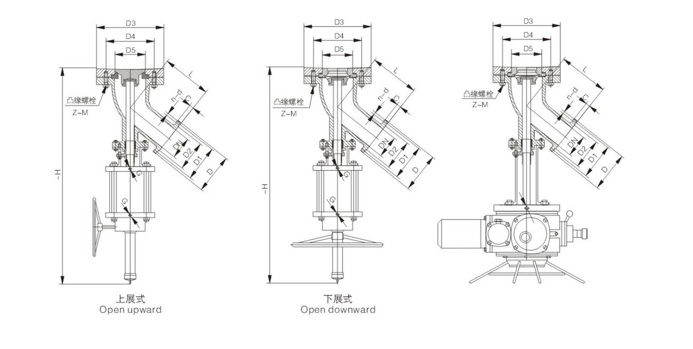
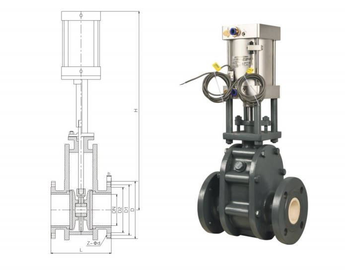
⍉ Bottom Outlet Design:Ideal for installation at the bottom of tanks or vessels
⍉ Reliable Sealing:Prevents leakage during operation
⍉ Smooth Flow Path:Reduces blockage and residue buildup.
⍉ Wide Application:Suitable for chemical, pharmaceutical, and food industries
⍉ Durable Construction:Corrosion-resistant for long service life