Product Overview
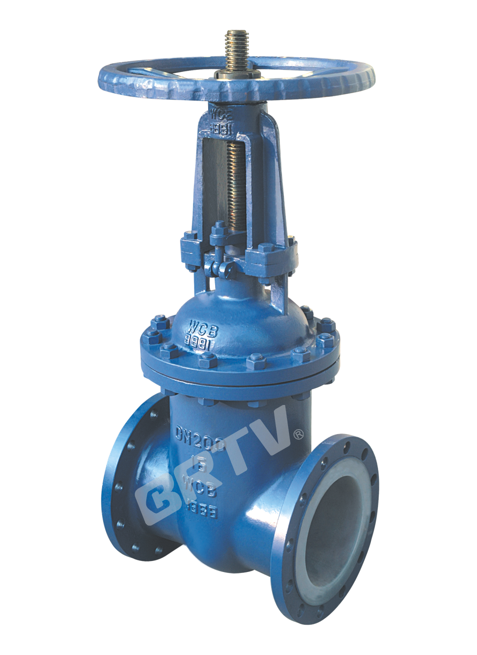
Fluorine Lined gate valve is the most common open-close valve, using the wedged sealing disc placed on the two sides to pass through or cut the medium in the pipeline. It can't be used as an adjusting flow device by slight opening, or the sealing face will be eroded and destroyed soon by high-speed medium.
Product Features
• Wedged gate valve has two kinds of shapes: flat and round. GB valves are round shape, ANSI lb class valve and DN ≤ 300 are flat shape, DN ≤ 400 are round shape. The cavity of body and bonnet and the outer face of disc and stem which contact the medium directly are coated with FEP (F46) or PCTFE (F3).
• The sealing pair is of FEP (F46) / PCTFE (F3), with small friction and low opening and closing torque.
• The packing with graphite has good sealing performance and convenient maintenance.
• The elastic wedge can compensate the wedge deviation between wedge sealing face and seat sealing face, providing good sealing performance.
• The medium can access the gate valve through any direction, suitable as an opening and closing device for pipelines where the direction of medium may change.
Executive standard
| Design and manufacture | GB 12234 / API 600 |
|---|
| Face to face | GB 12221 / ANSI B16.10 |
| Flange dimension | JB78/JB79 / ANSI B16.5 / GB9113.5 (PN4.0) / Or according to contract |
| Pressure test | GB/T 13927 / API 598 |
| Symbol | GB 12220 / API 600 |
| Supply | GB/T 12252 / API 600 |
Main Parts Material Specification
| No. | Part name | Grey cast iron (Z) | Carbon steel (C) | Stainless steel (P) | Stainless steel (R) | Low carbon SS (PL) | Low carbon SS (RL) |
|---|
| 1 | Body, Bonnet, Wedge | HT250 | WCB | CF8 | CF8M | CF3 | CF3M |
| 2 | Lining / Seat | - | PCTFE, PVDF, FEP, PFA, PO (common for all materials) | | | | |
| 3 | Stem | 1Cr13 | 2Cr13 | 1Cr18Ni9 | 1Cr18Ni12Mo2Ti | 00Cr18Ni10 | 00Cr17Ni14Mo2 |
| 4 | Packing, Gasket | - | Flexible graphite, PTFE (common for all materials) | | | | |
| 5 | Middle flange bolt | 35 | 35CrMoA | 1Cr17Ni2 | 1Cr17Ni2 | 1Cr18Ni9 | 1Cr18Ni9 |
| 6 | Middle flange nut | 45 | 45 | 0Cr18Ni9 | 0Cr18Ni9 | 0Cr18Ni9 | 0Cr18Ni9 |
| 7 | Yoke | - | HT250 / WCB / CF8 (shared) | | | | |
| 8 | Stem nut | - | ZCuAl10Fe3 | - | - | A439 D2 | - |
| 9 | Hand wheel | - | KT330-08 | - | - | QT400-15 | - |
Basic Type
| Operation Type | Model |
|---|
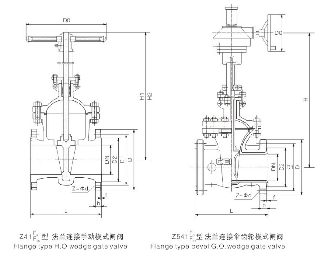
| Manually | Z41F₃ / Z41F₄₆ |
| Gear operated | Z441F₃ |
| Pneumatic | Z641F₃ / Z641F₄₆ |
| Electric | Z941F₃ / Z941F₄₆ |
Main Dimension
PN1.6(MPa)
| DN (mm) | NPS (in) | L | D | D1 | D2 | f | b | Z-Φd | Do | H1 | H2 | W (kg) |
|---|
| 15 | 1/2 | 140 | 95 | 65 | 45 | 2 | 14 | 4-Φ14 | 120 | 110 | 130 | 7 |
| 20 | 3/4 | 152 | 105 | 75 | 55 | 2 | 16 | 4-Φ14 | 120 | 120 | 140 | 8 |
| 25 | 1 | 165 | 115 | 85 | 65 | 2 | 16 | 4-Φ14 | 120 | 135 | 160 | 9 |
| 32 | 1-1/4 | 178 | 135 | 100 | 78 | 2 | 18 | 4-Φ18 | 160 | 160 | 190 | 13 |
| 40 | 1-1/2 | 240 | 145 | 110 | 85 | 3 | 18 | 4-Φ18 | 160 | 170 | 220 | 25 |
| 50 | 2 | 250 | 160 | 125 | 100 | 3 | 20 | 4-Φ18 | 160 | 360 | 410 | 32 |
| 65 | 2-1/2 | 270 | 180 | 145 | 120 | 3 | 20 | 4-Φ18 | 180 | 380 | 440 | 38 |
| 80 | 3 | 280 | 195 | 160 | 135 | 3 | 22 | 8-Φ18 | 180 | 440 | 520 | 50 |
| 100 | 4 | 300 | 215 | 180 | 155 | 3 | 24 | 8-Φ18 | 240 | 500 | 600 | 68 |
| 125 | 5 | 325 | 245 | 210 | 185 | 3 | 26 | 8-Φ18 | 240 | 615 | 740 | 125 |
| 150 | 6 | 350 | 280 | 240 | 210 | 3 | 28 | 8-Φ23 | 280 | 680 | 830 | 170 |
| 200 | 8 | 400 | 335 | 295 | 265 | 3 | 30 | 12-Φ23 | 280 | 820 | 1020 | 210 |
| 250 | 10 | 450 | 405 | 355 | 320 | 3 | 32 | 12-Φ25 | 320 | 980 | 1230 | 260 |
| 300 | 12 | 500 | 460 | 410 | 375 | 4 | 34 | 12-Φ25 | 320 | 1150 | 1450 | 480 |
| 350 | 14 | 550 | 520 | 470 | 435 | 4 | 38 | 16-Φ25 | 400 | 1285 | 1635 | 620 |
| 400 | 16 | 600 | 580 | 525 | 485 | 4 | 40 | 16-Φ30 | 400 | 1455 | 1855 | 805 |
| 450 | 18 | 650 | 640 | 585 | 545 | 4 | 44 | 20-Φ30 | 500 | 1545 | 1990 | 880 |
| 500 | 20 | 700 | 705 | 650 | 608 | 4 | 46 | 20-Φ34 | 500 | 1735 | 2235 | 920 |
PN2.5(MPa)
| DN (mm) | NPS (in) | L | D | D1 | D2 | f | b | Z-Φd | Do | H1 | H2 | W (kg) |
|---|
| 15 | 1/2 | 140 | 95 | 65 | 45 | 2 | 16 | 4-Φ14 | 120 | 110 | 130 | 8 |
| 20 | 3/4 | 152 | 105 | 75 | 55 | 2 | 16 | 4-Φ14 | 120 | 120 | 140 | 9 |
| 25 | 1 | 165 | 115 | 85 | 65 | 2 | 16 | 4-Φ14 | 160 | 135 | 160 | 10 |
| 32 | 1-1/4 | 178 | 135 | 100 | 78 | 2 | 18 | 4-Φ18 | 160 | 160 | 190 | 14 |
| 40 | 1-1/2 | 240 | 145 | 110 | 85 | 3 | 18 | 4-Φ18 | 180 | 170 | 220 | 28 |
| 50 | 2 | 250 | 160 | 125 | 100 | 3 | 20 | 4-Φ18 | 180 | 360 | 410 | 36 |
| 65 | 2-1/2 | 270 | 180 | 145 | 120 | 3 | 22 | 8-Φ18 | 240 | 380 | 440 | 45 |
| 80 | 3 | 280 | 195 | 160 | 135 | 3 | 22 | 8-Φ18 | 240 | 440 | 520 | 58 |
| 100 | 4 | 300 | 230 | 190 | 160 | 3 | 24 | 8-Φ23 | 280 | 500 | 600 | 76 |
| 125 | 5 | 325 | 270 | 220 | 188 | 3 | 28 | 8-Φ25 | 280 | 615 | 740 | 143 |
| 150 | 6 | 350 | 300 | 250 | 218 | 3 | 30 | 8-Φ25 | 320 | 680 | 830 | 178 |
| 200 | 8 | 400 | 360 | 310 | 278 | 3 | 34 | 12-Φ25 | 320 | 820 | 1020 | 243 |
| 250 | 10 | 450 | 425 | 370 | 332 | 3 | 36 | 12-Φ30 | 400 | 980 | 1230 | 275 |
| 300 | 12 | 500 | 485 | 430 | 390 | 4 | 40 | 16-Φ30 | 400 | 1150 | 1450 | 520 |
PN4.0(MPa)
| DN (mm) | NPS (in) | L | D | D1 | D2 | f | b | Z-Φd | Do | H1 | H2 | W (kg) |
|---|
| 15 | 1/2 | 108 | 89 | 60.5 | 35 | 2 | 12 | 4-Φ15 | 120 | 110 | 130 | 8 |
| 20 | 3/4 | 117 | 98 | 70 | 43 | 2 | 12 | 4-Φ15 | 120 | 120 | 140 | 9 |
| 25 | 1 | 127 | 108 | 79.5 | 51 | 2 | 12 | 4-Φ15 | 160 | 135 | 160 | 10 |
| 32 | 1-1/4 | 140 | 117 | 89 | 64 | 2 | 13 | 4-Φ15 | 160 | 160 | 190 | 13 |
| 40 | 1-1/2 | 165 | 127 | 98.5 | 73 | 2 | 15 | 4-Φ15 | 180 | 170 | 220 | 26 |
| 50 | 2 | 178 | 152 | 120.5 | 92 | 2 | 16 | 4-Φ19 | 180 | 360 | 410 | 34 |
| 65 | 2-1/2 | 190 | 178 | 139.5 | 105 | 2 | 18 | 4-Φ19 | 240 | 380 | 440 | 42 |
| 80 | 3 | 203 | 190 | 152.5 | 127 | 2 | 19 | 4-Φ19 | 240 | 440 | 520 | 54 |
| 100 | 4 | 229 | 229 | 190.5 | 157 | 2 | 24 | 8-Φ19 | 280 | 500 | 600 | 72 |
| 125 | 5 | 254 | 254 | 216 | 186 | 2 | 24 | 8-Φ22 | 280 | 615 | 740 | 132 |
| 150 | 6 | 267 | 279 | 241.5 | 216 | 2 | 26 | 8-Φ22 | 320 | 680 | 830 | 175 |
| 200 | 8 | 292 | 343 | 298.5 | 270 | 2 | 29 | 8-Φ22 | 320 | 820 | 1020 | 220 |
| 250 | 10 | 330 | 406 | 362 | 324 | 2 | 31 | 12-Φ25 | 400 | 980 | 1230 | 265 |
| 300 | 12 | 356 | 483 | 432 | 381 | 2 | 32 | 12-Φ25 | 400 | 1150 | 1450 | 490 |
| 350 | 14 | 381 | 533 | 476 | 413 | 2 | 35 | 12-Φ29 | 450 | 1285 | 1635 | 620 |
| 400 | 16 | 406 | 597 | 540 | 470 | 2 | 37 | 16-Φ29 | 450 | 1455 | 1855 | 810 |
| 450 | 18 | 432 | 635 | 578 | 533 | 2 | 40 | 16-Φ32 | 500 | 1545 | 1990 | 890 |
| 500 | 20 | 457 | 699 | 635 | 584 | 2 | 43 | 20-Φ32 | 500 | 1735 | 2235 | 940 |
| 600 | 24 | 508 | 813 | 749.5 | 692 | 2 | 48 | 20-Φ35 | 500 | 1850 | 2450 | 980 |
Manufacturing Process
Step 1: Order and Design
According to the customer's working conditions, including pressure, temperature, medium, and connection standard, the basic structure and lining requirements of the fluorine lined gate valve are confirmed. Drawings, material selection, and lining thickness are then finalized to ensure corrosion resistance and sealing performance.
Step 2: Forging & Casting
The main pressure-bearing parts such as body, bonnet, and gate are produced by casting or forging according to design requirements. For a fluorine lined gate valve, the castings must have good dimensional accuracy and surface quality, so as to meet the later lining and machining requirements.
Step 3: Machining
After casting inspection, all key parts are machined, including flange faces, sealing areas, stem hole, guide slot, and connection threads. During the machining of the fluorine lined gate valve, strict tolerance control is required to ensure smooth assembly and stable valve operation.
Step 4: Assembly
After machining and cleaning, fluorine-lined components are assembled together with stem, bonnet, packing, gasket, and fasteners. In the assembly process of the fluorine lined gate valve, special attention is paid to protecting the lining layer from scratches, deformation, or damage.
Step 5: Testing & Quality Assurance
Each fluorine lined gate valve must undergo pressure testing, sealing testing, lining inspection, and operation testing before delivery. Quality control is carried out throughout the whole process to ensure the valve meets design standards and customer requirements.
Step 6: Painting and Finishing
After final inspection, the external surface is painted, marked, and cleaned. Then the valve is packed properly for storage and shipment, ensuring good appearance and protection during transportation.
Applications
Operating temperature: 0–150°C. Resistant to corrosion from strong acids and alkalis. Primarily used in the petroleum, chemical, and pharmaceutical industries to control the flow of media such as hydrochloric acid and sulfuric acid.
These valves are widely used in:
Agriculture and Irrigation
Factory Environment
Why Choose Us
Superior Quality

Our valves are manufactured using premium materials and undergo rigorous quality testing to ensure reliable performance in demanding industrial applications.
Advanced Technology

Equipped with state-of-the-art CNC machining centers and precision manufacturing equipment, we deliver valves with exceptional accuracy and consistency.
Competitive Pricing

Through optimized manufacturing processes and bulk material procurement, we offer high-quality valves at competitive prices without compromising on quality.
Expert Support

Our experienced technical team provides comprehensive support from product selection to after-sales service, ensuring optimal valve performance for your specific application.