Product overview
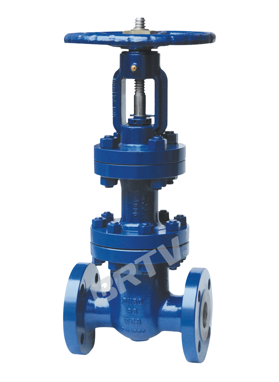
Gate valve with bellow seal acc. To GB is applicable to the cutting and connection of pipelines medium that are used in various industries such as petroleum, chemical industry, pharmacy, chemical fertilizer, electric power industry etc under nominal pressure of PN1.6 to 16MPa and working temperature of −29~350℃.
Product Features
- This product has logical structure, reliable seal, excellent performance and nice design.
- The seal surface is build-up welding with Co hard alloy, which is attrition-resistant, corrosion-resistant, has good friction resistant and long life.
- The stem is quenched and tempered, and its surface is treated by nit riding treatment, thus it has good corrosion resistant and friction resistant.
- It has double seal capability, thus is more reliable.
- The stem may show the position of lift, thus it is clearer.
- The part material, flange and butt weld end dimension may be selected according to current operating condition and users’ requirement, so that meet the requirements of various engineering.
Technical Specification
| Structural Formation | Driving Manner | Design Standard | Face to Face | Flange Ends | Test & Inspection |
|---|
| BB-BG-OS & Y | Hand-operated / Electric-actuated | GB12234 | GB12221 | GB9113; JB79; HG20596 | JB/T 9092; GB/T 13927 |
Products Performance Specification
| Nominal Pressure (MPa) | Shell Test (MPa) | Sealing Test (MPa) | Suitable Temp. (°C) | Suitable Medium |
|---|
| 1.6 | 2.4 | 1.76 | ≤350°C | Water, oil & gas |
| 2.5 | 3.75 | 2.75 | ≤350°C | Water, oil & gas |
| 4.0 | 6.0 | 4.4 | ≤350°C | Water, oil & gas |
| 6.4 | 9.6 | 7.04 | ≤350°C | Water, oil & gas |
Main Parts and Materials
| No. | Part Name | Material |
|---|
| 1 | Body | WCB, CF8, CF8M, CF3, CF3M |
| 2 | Disc | 25, 1Cr13, 2Cr13, 1Cr18Ni9Ti, 0Cr18Ni12Mo2Ti, 20Cr1Mo1V, 25Cr2MoV |
| 3 | Stem | 25, 1Cr13, 2Cr13, 1Cr18Ni9Ti, 0Cr18Ni12Mo2Ti, 20Cr1Mo1V, 25Cr2MoV |
| 4 | Bellow Assembly | 1Cr18Ni9Ti, 304, 316, 304L, 316L |
| 5 | Yoke | WCB, CF8, CF8M, CF3, CF3M |
| 6 | Gasket | Flexible graphite + stainless steel, PTFE |
| 7 | Bonnet | WCB, CF8, CF8M, CF3, CF3M |
| 8 | Nut | 0Cr18Ni9Ti, 0Cr18Ni12Mo2Ti, 35CrMoV, 25Cr2MoV |
| 9 | Bolt | 0Cr18Ni9Ti, 0Cr18Ni12Mo2Ti, 35CrMoV, 25Cr2MoV |
| 10 | Packing | Flexible graphite, PTFE |
| 11 | Gland | WCB, CF8, CF8M, CF3, CF3M |
| 12 | Yoke Nut | ZQA19-4 Copper Alloy |
| 13 | Handwheel | WCB QT400-18 |
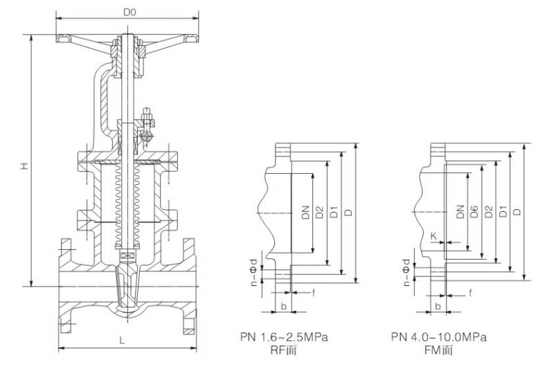
Main Dimension
Type: WZ41H-16C WZ41W-16P WZ41Y-16R
| DN | L | D | D1 | D2 | D6 | b | N-Φd | H | D0 | L2 | H1 | DA | Electric Actuator Code |
|---|
| 15 | 130 | 95 | 95 | 45 | - | 14 | 4-Φ14 | 190 | 120 | - | - | - | - |
| 20 | 150 | 105 | 75 | 55 | - | 14 | 4-Φ14 | 195 | 140 | - | - | - | - |
| 25 | 160 | 115 | 85 | 65 | - | 14 | 4-Φ14 | 225 | 140 | - | - | - | - |
| 32 | 180 | 135 | 100 | 78 | - | 16 | 4-Φ18 | 260 | 180 | - | - | - | - |
| 40 | 200 | 145 | 110 | 85 | - | 16 | 4-Φ18 | 280 | 200 | 590 | 595 | 365 | DZW10 |
| 50 | 250 | 160 | 125 | 100 | - | 16 | 4-Φ18 | 360 | 220 | 590 | 653 | 365 | DZW10 |
| 65 | 265 | 180 | 145 | 120 | - | 18 | 4-Φ18 | 375 | 260 | 590 | 665 | 365 | DZW10 |
| 80 | 280 | 195 | 160 | 135 | - | 20 | 8-Φ18 | 435 | 280 | 590 | 725 | 365 | DZW10 |
| 100 | 300 | 215 | 180 | 155 | - | 20 | 8-Φ18 | 500 | 300 | 590 | 787 | 365 | DZW15 |
| 125 | 325 | 245 | 210 | 185 | - | 22 | 8-Φ18 | 615 | 340 | 590 | 934 | 365 | DZW20 |
| 150 | 350 | 280 | 240 | 210 | - | 24 | 8-Φ23 | 675 | 400 | 590 | 955 | 365 | DZW20 |
| 200 | 400 | 335 | 295 | 265 | - | 26 | 12-Φ23 | 815 | 450 | 590 | 1105 | 365 | DZW20 |
| 250 | 450 | 405 | 355 | 320 | - | 30 | 12-Φ25 | 965 | 450 | 810 | 1343 | 470 | DZW30 |
| 300 | 500 | 460 | 410 | 375 | - | 30 | 12-Φ25 | 1145 | 500 | 810 | 1516 | 470 | DZW30 |
| 350 | 550 | 520 | 470 | 435 | - | 34 | 16-Φ25 | 1280 | 500 | 810 | 1678 | 470 | DZW45 |
| 400 | 600 | 580 | 525 | 485 | - | 36 | 16-Φ25 | 1450 | 560 | 830 | 1849 | 550 | DZW90 |
| 450 | 650 | 640 | 585 | 545 | - | 40 | 20-Φ30 | 1540 | 600 | 830 | 1937 | 550 | DZW120 |
| 500 | 700 | 705 | 650 | 608 | - | 44 | 20-Φ34 | 1675 | 640 | 830 | 2234 | 550 | DZW120 |
| 600 | 800 | 840 | 770 | 718 | - | 48 | 20-Φ41 | 1875 | 720 | 870 | 2432 | 320 | DZW180 |
| 700 | 900 | 910 | 840 | 788 | - | 50 | 24-Φ41 | 2085 | 800 | 870 | 2489 | 320 | DZW250 |
| 800 | 1000 | 1020 | 950 | 898 | - | 52 | 24-Φ41 | 2400 | 950 | 1170 | 2643 | 570 | DZW250 |
Type: WZ41H-25C WZ41W-25P WZ41Y-25R
| DN | L | D | D1 | D2 | D6 | b | N-Φd | H | D0 | L2 | H1 | DA | Electric Actuator Code |
|---|
| 15 | 130 | 95 | 65 | 45 | - | 16 | 4-Φ14 | 190 | 120 | - | - | - | - |
| 20 | 150 | 105 | 75 | 55 | - | 16 | 4-Φ14 | 195 | 140 | - | - | - | - |
| 25 | 160 | 115 | 85 | 65 | - | 16 | 4-Φ14 | 225 | 140 | - | - | - | - |
| 32 | 180 | 135 | 100 | 78 | - | 18 | 4-Φ18 | 260 | 180 | - | - | - | - |
| 40 | 200 | 145 | 110 | 85 | - | 18 | 4-Φ18 | 280 | 200 | 590 | 595 | 365 | DZW10 |
| 50 | 250 | 160 | 125 | 100 | - | 20 | 4-Φ18 | 360 | 220 | 590 | 653 | 365 | DZW10 |
| 65 | 265 | 180 | 145 | 120 | - | 22 | 8-Φ18 | 375 | 260 | 590 | 665 | 365 | DZW10 |
| 80 | 280 | 195 | 160 | 135 | - | 22 | 8-Φ18 | 435 | 280 | 590 | 725 | 365 | DZW15 |
| 100 | 300 | 230 | 190 | 160 | - | 24 | 8-Φ23 | 500 | 300 | 590 | 787 | 365 | DZW20 |
| 125 | 325 | 270 | 220 | 188 | - | 28 | 8-Φ25 | 615 | 340 | 590 | 902 | 365 | DZW20 |
| 150 | 350 | 300 | 250 | 218 | - | 30 | 8-Φ25 | 675 | 400 | 590 | 955 | 365 | DZW20 |
| 200 | 400 | 360 | 310 | 278 | - | 34 | 12-Φ25 | 815 | 450 | 810 | 1105 | 470 | DZW30 |
| 250 | 450 | 425 | 370 | 332 | - | 36 | 12-Φ30 | 965 | 450 | 810 | 1343 | 470 | DZW30 |
| 300 | 500 | 485 | 430 | 390 | - | 40 | 16-Φ30 | 1145 | 500 | 810 | 1516 | 470 | DZW60 |
| 350 | 550 | 550 | 490 | 448 | - | 44 | 16-Φ34 | 1280 | 500 | 830 | 1678 | 550 | DZW90 |
| 400 | 600 | 610 | 550 | 505 | - | 48 | 16-Φ34 | 1450 | 560 | 830 | 1849 | 550 | DZW120 |
| 450 | 650 | 660 | 600 | 555 | - | 50 | 20-Φ34 | 1540 | 600 | 830 | 1937 | 550 | DZW120 |
| 500 | 700 | 730 | 660 | 610 | - | 52 | 20-Φ41/36 | 1675 | 640 | 870 | 2234 | 320 | DZW180 |
| 600 | 800 | 840 | 770 | 718 | - | 56 | 20-Φ41 | 1875 | 720 | 870 | 2432 | 320 | DZW250 |
| 700 | 900 | 955 | 875 | 815 | - | 60 | 24-Φ48/42 | 2085 | 800 | 870 | 2489 | 320 | DZW500 |
| 800 | 1000 | 1070 | 990 | 930 | - | 64 | 24-Φ48 | 2400 | 950 | 1170 | 2643 | 570 | DZW500 |
Type: WZ41H-40C WZ41W-40P WZ41Y-40R
| DN | L | D | D1 | D2 | D6 | b | N-Φd | H | D0 | L2 | H1 | DA | Electric Actuator Code |
|---|
| 15 | 130 | 95 | 65 | 45 | - | 16 | 4-Φ14 | 190 | 120 | - | - | - | - |
| 20 | 150 | 105 | 75 | 55 | - | 16 | 4-Φ14 | 195 | 140 | - | - | - | - |
| 25 | 160 | 115 | 85 | 65 | - | 16 | 4-Φ14 | 225 | 140 | - | - | - | - |
| 32 | 180 | 135 | 100 | 78 | - | 18 | 4-Φ18 | 270 | 180 | - | - | - | - |
| 40 | 200 | 145 | 110 | 85 | - | 18 | 4-Φ18 | 320 | 220 | 590 | 630 | 365 | DZW10 |
| 50 | 250 | 160 | 125 | 100 | - | 20 | 4-Φ18 | 370 | 240 | 590 | 691 | 365 | DZW10 |
| 65 | 280 | 180 | 145 | 120 | - | 22 | 8-Φ18 | 395 | 280 | 590 | 711 | 365 | DZW10 |
| 80 | 310 | 195 | 160 | 135 | - | 22 | 8-Φ18 | 455 | 300 | 590 | 775 | 365 | DZW15 |
| 100 | 350 | 230 | 190 | 160 | - | 24 | 8-Φ23 | 550 | 320 | 590 | 871 | 365 | DZW20 |
| 125 | 400 | 270 | 220 | 188 | - | 28 | 8-Φ25 | 635 | 350 | 590 | 948 | 365 | DZW20 |
| 150 | 450 | 300 | 250 | 218 | - | 30 | 8-Φ25 | 705 | 400 | 810 | 1028 | 470 | DZW30 |
| 200 | 550 | 375 | 320 | 282 | - | 38 | 12-Φ30 | 860 | 450 | 810 | 1325 | 470 | DZW30 |
| 250 | 650 | 445 | 385 | 345 | - | 42 | 12-Φ34 | 1015 | 560 | 810 | 1400 | 470 | DZW45 |
| 300 | 750 | 510 | 450 | 408 | - | 46 | 16-Φ34 | 1200 | 640 | 830 | 1653 | 550 | DZW60 |
| 350 | 850 | 570 | 510 | 465 | - | 52 | 16-Φ34 | 1340 | 640 | 830 | 1791 | 550 | DZW90 |
| 400 | 950 | 655 | 585 | 535 | - | 58 | 16-Φ41 | 1495 | 720 | 870 | 2092 | 320 | DZW120 |
| 450 | 1050 | 680 | 610 | 560 | - | 60 | 20-Φ41 | 1580 | 800 | - | - | - | - |
| 500 | 1150 | 755 | 670 | 612 | - | 62 | 20-Φ48/42 | 1700 | 950 | 870 | 2465 | 320 | DZW250 |
| 600 | 1350 | 890 | 795 | 730 | - | 62 | 20-Φ54/48 | 1950 | 950 | 1170 | - | 570 | DZW350 |
| 700 | 1450 | 995 | 900 | 835 | - | 68 | 24-Φ54/48 | 2250 | 1000 | 1170 | - | 570 | DZW500 |
| 800 | 1650 | 1135 | 1030 | 960 | - | 76 | 24-Φ58 | 2480 | 1100 | 1060 | - | 500 | DZW800 |
Manufacturing Process
Step 1: Order and Design
Based on the customer’s specifications for pressure rating, nominal diameter, material, and connection type, the structural design of the bellows gate valve is determined. Drawings, bills of materials, and manufacturing processes are finalized to ensure the product complies with relevant standards such as DIN, ANSI, or GB.
Step 2: Forging & Casting
Major pressure-bearing components, such as the valve body and bonnet, are formed using forging or casting processes to ensure the bellows gate valve possesses excellent strength and sealing reliability. Upon arrival, raw materials undergo material testing, and blanks are subjected to initial inspections for appearance and dimensions.
Step 3: Machining
Precision machining is performed on the valve body, bonnet, gate, stem, and sealing surfaces. Key machining areas for the bellows gate valve include the sealing surfaces, stem threads, flange faces, and bellows connection points to ensure assembly accuracy and operational stability.
Step 4: Assembly
Machined components undergo cleaning and deburring before proceeding to the assembly process. During assembly, the focus is on installing the bellows assembly, valve stem, gate, and seals to ensure the bellows gate valve possesses excellent double-seal performance and smooth opening and closing.
Step 5: Testing & Quality Assurance
After assembly, the bellows gate valve undergoes shell strength testing, seal testing, back-seal testing, and bellows leakage detection. Simultaneously, dimensional re-inspection, visual inspection, and opening/closing torque testing are conducted to ensure the product meets quality standards.
Step 6: Painting and Finishing
After passing inspection, the valve surface undergoes rust removal, painting, and marking. Finally, the nameplate is installed, and the valve is packaged and subjected to a pre-shipment inspection. This ensures the product has a clean appearance, excellent corrosion resistance, and meets the requirements for transportation and on-site use.
Applications
This valve is widely used in the petrochemical, power generation, pharmaceutical and food, natural gas, vacuum systems, and environmental protection and metallurgy industries. It is particularly suitable for applications involving the conveyance of high-temperature, high-pressure, flammable, explosive, toxic, or corrosive media, as well as those requiring high purity. Its key advantage lies in its bellows-sealed design, which effectively prevents media leakage along the valve stem. This not only enhances the safety and reliability of system operation but also helps reduce environmental pollution and energy waste.
These valves are widely used in:
Agriculture and Irrigation
Factory Environment
Why Choose Us
Superior Quality

Our valves are manufactured using premium materials and undergo rigorous quality testing to ensure reliable performance in demanding industrial applications.
Advanced Technology

Equipped with state-of-the-art CNC machining centers and precision manufacturing equipment, we deliver valves with exceptional accuracy and consistency.
Competitive Pricing

Through optimized manufacturing processes and bulk material procurement, we offer high-quality valves at competitive prices without compromising on quality.
Expert Support

Our experienced technical team provides comprehensive support from product selection to after-sales service, ensuring optimal valve performance for your specific application.