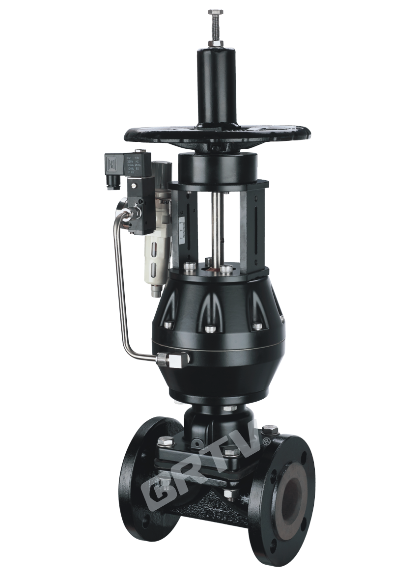
G41F46 Diaphragm Valve
Diaphragm valve is a special form of valve with truncation function, its opening and closing parts composed of a diaphragm of steel disc and a soft material (rubber and fluoroplastic compound). The inner cavity of the valve body is separated from the inner cavity of the valve cover to cut off the medium in the pipe.
The Series of Lined Fluoroplastics Diaphragm Valve
The basic series of diaphragm valve includes G41F46 weir–type, EG41F46 weir–type, and G45F46 straight flow type. Its features are as follows:
1.The composite diaphragm separates the lower body chamber from the bonnet chamber and forms a direct current channel with it, which can completely isolate the upper part of the diaphragm stem, disc and other internal parts and media, saves seal packing, avoids internal leakage and external leakage of the medium at the same time.
2.The diaphragm is composed of FEP (Teflon) fluoroplastic and synthetic rubber. The valve is with lined (Teflon) fluoroplastic. Both of them are suitable for a variety of highly corrosive media except for "molten alkali metals and elements".
3.As the diaphragm of the actuator, it is prone to fatigue fracture due to frequent opening and closing. The diaphragm shall be replaced periodically in terms of test condition, medium and characteristics.
4.As for the corrosion resistance and recommended temperature, please refer to the "fluorine for valve and pipeline accessories" and "lined fluoroplastics performance sheet".
Technique Standard
| Design and Manufacture | GB/T 12239 |
|---|
| Structure Length | GB/T 12221, HG/T 37004 |
| Flange Dimensions | HG/T 20592 |
| Pressure Test | GB/T 13927 |
| Mark | GB/T 12220 |
| Supply | GB/T 12252 |
Basic Model
| Manual (Type) | Manual (Type) | Electric (Type) |
|---|
| G41F3 (weir type) | G641F3 (reciprocating) | G9B41F3 (explosion-proof) |
| G41F46 (weir type) | G641F46 (reciprocating) | G9B41F46 (explosion-proof) |
| G45F3 (straight flow type) | G6B41F3 (normally closed) | G941F3 (standard type) |
| G45F46 (straight flow type) | G6B41F46 (normally closed) | G941F46 (standard type) |
Main Component Materials
| Components | Gray Cast Iron (Z) | Carbon Steel (C) | Stainless Steel (P) | Stainless Steel (R) | Ultra-low Carbon Stainless Steel (RL) | Ultra-low Carbon Stainless Steel (RL) |
|---|
| Body, Cover, Disc | HT250 | WCB | CF8 | CF8M | CF3 | CF3M |
| Stem | 35 | 1Cr13 | 1Cr18Ni9 | 1Cr18Ni12Mo2Ti | 00Cr18Ni10 | 00Cr17Ni14Mo2 |
| Lining | FEP (F46), PFA, PCTFE (F3), PO (Polyolefin) | FEP (F46), PFA, PCTFE (F3), PO (Polyolefin) | FEP (F46), PFA, PCTFE (F3), PO (Polyolefin) | FEP (F46), PFA, PCTFE (F3), PO (Polyolefin) | FEP (F46), PFA, PCTFE (F3), PO (Polyolefin) | FEP (F46), PFA, PCTFE (F3), PO (Polyolefin) |
| Diaphragm | FEP (F46)/CR (Chloroprene Rubber), PFA/FPM (Fluororubber) | FEP (F46)/CR (Chloroprene Rubber), PFA/FPM (Fluororubber) | FEP (F46)/CR (Chloroprene Rubber), PFA/FPM (Fluororubber) | FEP (F46)/CR (Chloroprene Rubber), PFA/FPM (Fluororubber) | FEP (F46)/CR (Chloroprene Rubber), PFA/FPM (Fluororubber) | FEP (F46)/CR (Chloroprene Rubber), PFA/FPM (Fluororubber) |
| Stem Nut | ZCuAl10Fe3 | ZCuAl10Fe3 | ZCuAl10Fe3 | ZCuAl10Fe3 | ZCuAl10Fe3 | ZCuAl10Fe3 |
| Bolt | 35 | 35 | 1Cr17Ni2 | 1Cr17Ni2 | 1Cr17Ni2 | 1Cr17Ni9Ti |
| Nut | 45 | 45 | 0Cr18Ni9 | 0Cr18Ni9 | 0Cr18Ni9 | 0Cr18Ni9 |
| Handwheel | HT200 | HT200 | WCC | WCC | WCC | WCC |
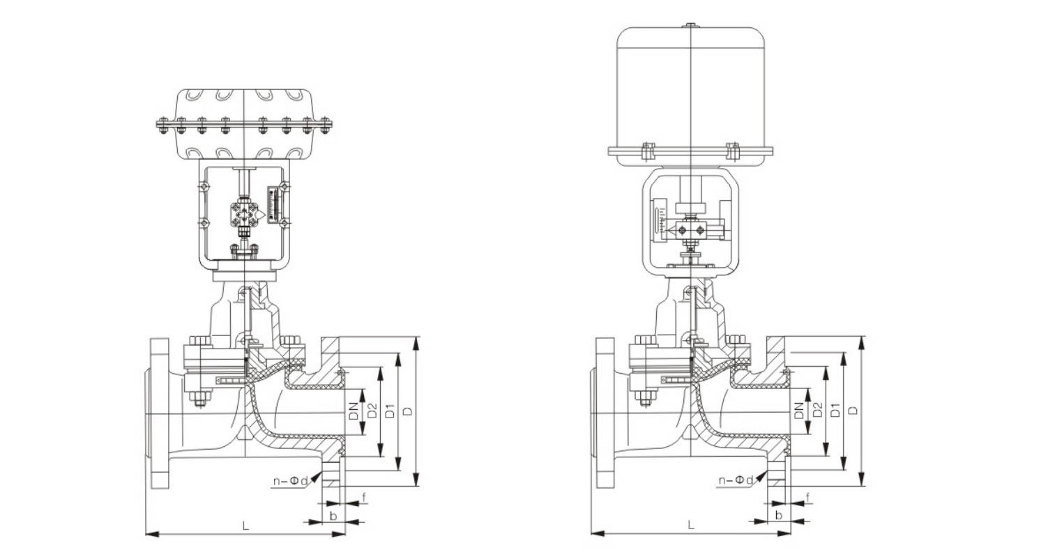
Main Outline and Connecting Flange Size
ZTG641F(F4/F46)-PN10(1.0MPa)
| DN | in | L | D | D1 | D2 | f | b | N-Φd | Pneumatic Actuator Model | Electric Actuator Model |
|---|
| 15 | 1/2 | 125 | 95 | 65 | 45 | 2 | 14 | 4-Φ14 | ZJHA/B-22 | 381L-20 |
| 20 | 3/4 | 135 | 105 | 75 | 55 | 2 | 16 | 4-Φ14 | ZJHA/B-22 | 381L-20 |
| 25 | 1 | 145 | 115 | 85 | 65 | 2 | 16 | 4-Φ14 | ZJHA/B-22 | 381L-20 |
| 32 | 1 1/4 | 160 | 140 | 100 | 78 | 2 | 18 | 4-Φ18 | ZJHA/B-23 | 381L-30 |
| 40 | 1 1/2 | 180 | 150 | 110 | 85 | 3 | 18 | 4-Φ18 | ZJHA/B-23 | 381L-30 |
| 50 | 2 | 210 | 165 | 125 | 100 | 3 | 20 | 4-Φ18 | ZJHA/B-23 | 381L-30 |
| 65 | 2 1/2 | 250 | 185 | 145 | 120 | 3 | 20 | 4-Φ18 | ZJHA/B-34 | 381L-50 |
| 80 | 3 | 300 | 200 | 160 | 135 | 3 | 22 | 4/8-Φ18 | ZJHA/B-34 | 381L-50 |
| 100 | 4 | 350 | 220 | 180 | 155 | 3 | 22 | 8-Φ18 | ZJHA/B-34 | 381L-50 |
| 125 | 5 | 400 | 250 | 210 | 185 | 3 | 24 | 8-Φ18 | ZJHA/B-45 | 381L-65 |
| 150 | 6 | 460 | 285 | 240 | 210 | 3 | 24 | 8-Φ23 | ZJHA/B-45 | 381L-65 |
| 200 | 8 | 570 | 340 | 295 | 265 | 3 | 26 | 8-Φ23 | ZJHA/B-45 | 381L-65 |
| 250 | 10 | 680 | 395 | 350 | 320 | 3 | 28 | 12-Φ23 | ZJHA/B-56 | 381L-99 |
| 300 | 12 | 790 | 445 | 400 | 368 | 4 | 28 | 12-Φ23 | ZJHA/B-56 | 381L-99 |
ZTG641F(F4/F46)-PN16(1.6MPa)
| DN | in | L | D | D1 | D2 | f | b | N-Φd | Pneumatic Actuator Model | Electric Actuator Model |
|---|
| 15 | 1/2 | 125 | 95 | 65 | 45 | 2 | 14 | 4-Φ14 | ZJHA/B-22 | 381L-30 |
| 20 | 3/4 | 135 | 105 | 75 | 55 | 2 | 16 | 4-Φ14 | ZJHA/B-22 | 381L-30 |
| 25 | 1 | 145 | 115 | 85 | 65 | 2 | 16 | 4-Φ14 | ZJHA/B-22 | 381L-30 |
| 32 | 1 1/4 | 160 | 140 | 100 | 78 | 2 | 18 | 4-Φ18 | ZJHA/B-23 | 381L-50 |
| 40 | 1 1/2 | 180 | 150 | 110 | 85 | 3 | 18 | 4-Φ18 | ZJHA/B-23 | 381L-50 |
| 50 | 2 | 210 | 165 | 125 | 100 | 3 | 20 | 4-Φ18 | ZJHA/B-23 | 381L-50 |
| 65 | 2 1/2 | 250 | 185 | 145 | 120 | 3 | 20 | 4-Φ18 | ZJHA/B-34 | 381L-65 |
| 80 | 3 | 300 | 200 | 160 | 135 | 3 | 22 | 8-Φ18 | ZJHA/B-34 | 381L-65 |
| 100 | 4 | 350 | 220 | 180 | 155 | 3 | 24 | 8-Φ18 | ZJHA/B-34 | 381L-65 |
| 125 | 5 | 400 | 250 | 210 | 185 | 3 | 26 | 8-Φ18 | ZJHA/B-45 | 381L-99 |
| 150 | 6 | 460 | 285 | 240 | 210 | 3 | 28 | 8-Φ23 | ZJHA/B-45 | 381L-99 |
| 200 | 8 | 570 | 340 | 295 | 265 | 3 | 30 | 12-Φ23 | ZJHA/B-45 | 381L-99 |
| 250 | 10 | 680 | 395 | 355 | 320 | 3 | 32 | 12-Φ25 | ZJHA/B-56 | 381L-160 |
| 300 | 12 | 790 | 445 | 410 | 375 | 4 | 34 | 12-Φ25 | ZJHA/B-56 | 381L-160 |
Product Overview
Fluorine lined diaphragm valve is designed for shut-off applications. Its opening and closing element is composed of a metal disc combined with soft materials, and the body cavity is separated from the bonnet cavity to isolate and cut off the medium.
The main series include G41F46 weir-type diaphragm valves and G45F46 straight-through diaphragm valves. Their characteristics are as follows:
Product Features
• A complex diaphragm structure separates the lower body cavity from the bonnet cavity, isolating the stem, disc, and medium. This eliminates the need for packing and prevents both internal and external leakage.
• The diaphragm is made of fluoroplastic-lined FEP combined with synthetic rubber. The valve body is also fluoroplastic-lined, making it suitable for highly corrosive media, except molten alkali metals and elemental fluorine.
• The diaphragm acts as the operating element and may be prone to fatigue or cracking due to frequent opening and closing, so regular inspection and replacement are required.
• The fluoroplastic lining provides excellent corrosion resistance. Recommended operating temperatures should follow the specifications for fluoroplastic-lined valves and piping accessories.
Executive Standard
| Design and manufacture | GB 12239 |
|---|
| Face to face | JB 1688 |
| Flange dimension | JB 78 (or according to contract) |
| Pressure test | GB/T 13927 |
| Symbol | GB 12220 |
| Supply | GB/T 12252 |
Main Parts Material Specifications
| No. | Parts name | Grey cast iron (Z) | Carbon steel (C) | Stainless steel (P) | Stainless steel (R) | Low carbon SS (PL) | Low carbon SS (RL) |
|---|
| 1 | Body, Bonnet, Disc | HT250 | WCB | CF8 | CF8M | CF3 | CF3M |
| 2 | Stem | 35 | 1Cr13 | 1Cr18Ni9 | 1Cr18Ni12Mo12Ti | 00Cr18Ni10 | 00Cr17Ni14Mo2 |
| 3 | Lining | — | FEP / PFA / PCTFE | — | — | PO | — |
| 4 | Diaphragm | — | FEP/CR | PFA/FPDM | — | — | — |
| 5 | Stem nuts | — | ZCuAl10Fe3 | ZCuAl10Fe3 | — | — | — |
| 6 | Bolt | 35 | 35CrMoA | 1Cr17Ni2 | 1Cr17Ni2 | 1Cr17Ni2 | 1Cr17Ni2 |
| 7 | Nut | 45 | 45 | 0Cr18Ni9 | 0Cr18Ni9 | 0Cr18Ni9 | 0Cr18Ni9 |
| 8 | Handwheel | HT200 | HT200 | WCC | WCC | WCC | WCC |

Basic Type
| Operation Type | Model | Description |
|---|
| Manually | G41F | Weir type |
| Manually | G45F | Y type |
| Pneumatic | G641F | Reciprocating type |
| Pneumatic | G6B41F | Close type |
| Electric | G9B41F | Explosion-proof type |
| Electric | G941F | General type |
Main Dimension
PN1.0 MPa / PN0.6 MPa
| DN (mm) | NPS (inch) | L | D | D1 | D2 | f | b | Z-Φd | DO | H1 | H2 | W (kg) |
|---|
| 15 | 1/2 | 125 | 95 | 65 | 45 | 2 | 14 | 4-Φ14 | 100 | 105 | 110 | 3.5 |
| 20 | 3/4 | 135 | 105 | 75 | 55 | 2 | 16 | 4-Φ14 | 100 | 115 | 125 | 4 |
| 25 | 1 | 145 | 115 | 85 | 65 | 2 | 16 | 4-Φ14 | 120 | 120 | 135 | 5.5 |
| 32 | 1 1/4 | (160) | 135 | 100 | 78 | 2 | 18 | 4-Φ18 | 120 | 125 | 150 | 8 |
| 40 | 1 1/2 | 180 | 145 | 110 | 85 | 3 | 18 | 4-Φ18 | 140 | 135 | 175 | 11 |
| 50 | 2 | 210 | 160 | 125 | 100 | 3 | 20 | 4-Φ18 | 140 | 155 | 195 | 14 |
| 65 | 2 1/2 | 250 | 180 | 145 | 120 | 3 | 20 | 4-Φ18 | 200 | 170 | 200 | 23 |
| 80 | 3 | 300 | 195 | 160 | 135 | 3 | 22 | 4/8-Φ18 | 200 | 200 | 255 | 29 |
| 100 | 4 | 350 | 215 | 180 | 155 | 3 | 22 | 8-Φ18 | 280 | 270 | 325 | 46 |
| 125 | 5 | 400 | 245 | 210 | 185 | 3 | 24 | 8-Φ18 | 320 | 335 | 405 | 70 |
| 150 | 6 | 460 | 280 | 240 | 210 | 3 | 24 | 8-Φ23 | 320 | 370 | 450 | 95 |
| 200 | 8 | 570 | 335 | 295 | 265 | 3 | 26 | 8-Φ23 | 400 | 480 | 600 | 170 |
| 250 | 10 | 680 | 390 | 350 | 320 | 3 | 28 | 12-Φ23 | 500 | 545 | 620 | 270 |
| 300 | 12 | 790 | 440 | 400 | 368 | 4 | 28 | 12-Φ23 | 500 | 585 | 680 | 320 |
PN1.6 MPa
| DN (mm) | NPS (inch) | L | D | D1 | D2 | f | b | Z-Φd | DO | H1 | H2 | W (kg) |
|---|
| 15 | 1/2 | 125 | 95 | 65 | 45 | 2 | 14 | 4-Φ14 | 120 | 110 | 115 | 4 |
| 20 | 3/4 | 135 | 105 | 75 | 55 | 2 | 16 | 4-Φ14 | 120 | 120 | 130 | 5 |
| 25 | 1 | 145 | 115 | 85 | 65 | 2 | 16 | 4-Φ14 | 140 | 125 | 140 | 6 |
| 32 | 1 1/4 | (160) | 135 | 100 | 78 | 2 | 18 | 4-Φ18 | 140 | 130 | 155 | 9 |
| 40 | 1 1/2 | 180 | 145 | 110 | 85 | 3 | 18 | 4-Φ18 | 160 | 140 | 180 | 12 |
| 50 | 2 | 210 | 160 | 125 | 100 | 3 | 20 | 4-Φ18 | 160 | 160 | 200 | 15 |
| 65 | 2 1/2 | 250 | 180 | 145 | 120 | 3 | 20 | 4-Φ18 | 200 | 175 | 205 | 24 |
| 80 | 3 | 300 | 195 | 160 | 135 | 3 | 22 | 4-Φ18 | 200 | 205 | 260 | 30 |
| 100 | 4 | 350 | 215 | 180 | 155 | 3 | 24 | 8-Φ18 | 280 | 275 | 330 | 48 |
| 125 | 5 | 400 | 245 | 210 | 185 | 3 | 26 | 8-Φ18 | 320 | 340 | 410 | 75 |
| 150 | 6 | 460 | 280 | 240 | 210 | 3 | 28 | 8-Φ23 | 320 | 375 | 460 | 105 |
| 200 | 8 | 570 | 335 | 295 | 265 | 3 | 30 | 8-Φ23 | 400 | 485 | 605 | 182 |
| 250 | 10 | 680 | 405 | 355 | 320 | 3 | 32 | 12-Φ25 | 500 | 550 | 625 | 295 |
| 300 | 12 | 790 | 460 | 410 | 375 | 3 | 34 | 12-Φ25 | 500 | 590 | 685 | 345 |
Manufacturing Process
Step 1: Order and Design
Confirm the customer’s requirements, including size, pressure rating, flange standard, body material, and lining material. According to the working conditions such as corrosive media and temperature, the design team prepares the production drawing and technical plan for the fluorine lined diaphragm valve.
Step 2: Forging & Casting
The main pressure-bearing parts such as valve body, bonnet, and other metal components are produced by casting or forging based on the design requirements. Raw materials are inspected first to ensure strength and chemical composition meet the standards for fluorine lined diaphragm valve manufacturing.
Step 3: Machining
After casting or forging, all parts enter machining. This includes CNC machining of the valve body cavity, flange faces, bolt holes, stem connection parts, and sealing-related areas. Accurate machining is essential to ensure assembly precision and stable operation of the fluorine lined diaphragm valve.
Step 4: Assembly
After cleaning and inspection, the fluorine-lined body, diaphragm, stem, bonnet, handwheel or actuator are assembled in sequence. During this stage, special attention is given to diaphragm installation and sealing surface protection to guarantee reliable sealing performance of the fluorine lined diaphragm valve.
Step 5: Testing & Quality Assurance
Each valve undergoes pressure testing, sealing testing, lining inspection, dimension inspection, and visual inspection. For every fluorine lined diaphragm valve, the factory verifies smooth operation, leak-tight performance, and full compliance with technical specifications before delivery.
Step 6: Painting and Finishing
After final inspection, the external metal surface is cleaned, painted, and marked. Then the valve is packed with product labels, inspection documents, and protective materials to ensure safe transportation and neat final delivery.
Applications
This valve is primarily used in the chemical and pharmaceutical industries. It is suitable for low-pressure environments of up to 1.6 MPa and a temperature range of -50°C to +150°C. It can handle corrosive media such as strong acids and strong alkalis, but is not suitable for organic solvents or high-temperature, high-pressure applications.
These valves are widely used in:
Agriculture and Irrigation
Factory Environment
Why Choose Us
Superior Quality

Our valves are manufactured using premium materials and undergo rigorous quality testing to ensure reliable performance in demanding industrial applications.
Advanced Technology

Equipped with state-of-the-art CNC machining centers and precision manufacturing equipment, we deliver valves with exceptional accuracy and consistency.
Competitive Pricing

Through optimized manufacturing processes and bulk material procurement, we offer high-quality valves at competitive prices without compromising on quality.
Expert Support

Our experienced technical team provides comprehensive support from product selection to after-sales service, ensuring optimal valve performance for your specific application.