Function
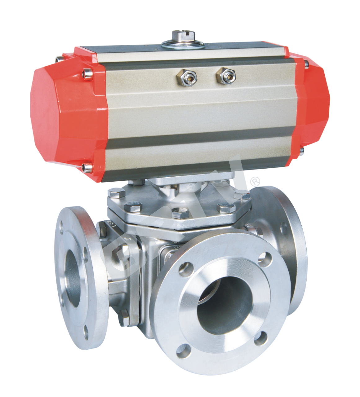
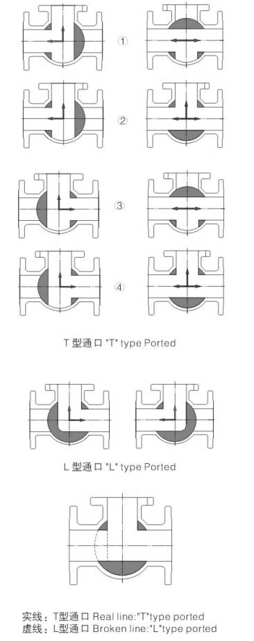
Three-way ball valves are used to switch over, mix and divide the flow of corrosive or non corrosive liquid, gas or powdery mediums. Upon opening and closing, the smooth flow channel effects less pressure loss, making operation quite labor-saving and maintenance fairly easy. The five types of flow direction (figure on the right, 1 for L-shaped and 4 for T-shaped) to meet different technological requirements. It can be hand, air and electrically operated.
Structural Features
-
Valve seat can be designed into four-side seated float ball and fixed ball, with smooth fluid state and reliable seal:
-
The structure can be designed into side entry type and top entry type, with two way seal, no series flow upon switch over of flow direction;
-
Anti-blowout design of valve stem;
-
Antistatic design;
-
Two position (ON and OFF) lockup design.
Three Way Ball Valve Manufacture Norms
| Category | API Series | DIN Series |
|---|
| Design Standards | ANSI B16.34 | ANSI B16.34 |
| Pressure / Temperature Rating | ANSI B16.34 | DIN 3356 |
| Face to Face Dimensions | ASME B16.10 | ASME B16.10 |
| Flange Ends | ASME B16.5 | DIN 2543–2551 |
| Inspection and Test | API 598 | DIN 3230 |
Main Parts Materials
| No. | Part Name |
|---|
| 1 | Body |
| 2 | Ball |
| 3 | O-Ring |
| 4 | Adapter |
| 5 | Seat Ring |
| 6 | Gasket |
| 7 | Bolt |
| 8 | Nut |
| 9 | Bonnet |
| 10 | Seat Retainer |
| 11 | Stem |
| 12 | Stem Packing |
| 13 | Packing Gland |
| 14 | Stop Screw |
| 15 | Stop Plate |
| 16 | Set Screw |
| 17 | Lever |
1. Flanged Three Way Ball Valve
Technique Standard
| Design Basis | GB Standard | ANSI Standard |
|---|
| Design standard | GB/T 12237 | ANSI B16.34 |
| Connecting Flange Size | GB/T 9113, JB/T 79 | ANSI B16.5 |
| Test & inspection | JB/T 9092 | API 598 |
Form of Main Parts Materials
| Name of Parts | C | P | R |
|---|
| Right Valve | WCB | ZG1Cr18Ni9Ti | ZG1Cr18Ni12Mo2Ti |
| Nut | 35 | 1Cr18Ni9Ti | 1Cr18Ni9Ti |
| Gasket | PTFE, Graphite metal composite pad | PTFE, Graphite metal composite pad | PTFE, Graphite metal composite pad |
| Screw | 35 | 1Cr18Ni9Ti | 1Cr18Ni9Ti |
| Body | WCB | ZG1Cr18Ni9Ti | ZG1Cr18Ni12Mo2Ti |
| Seat | PTFE, Nylon, Para-polyphenylene, Cemented carbide | PTFE, Nylon, Para-polyphenylene, Cemented carbide | PTFE, Nylon, Para-polyphenylene, Cemented carbide |
| Ball | 1Cr18Ni9Ti | 1Cr18Ni9Ti | 1Cr18Ni12Mo2Ti |
| Stem | 1Cr13 | 1Cr18Ni9Ti | 1Cr18Ni12Mo2Ti |
| Gasket | 1Cr18Ni9Ti | 1Cr18Ni9Ti | 1Cr18Ni12Mo2Ti |
| Packing | PTFE, Flexible Graphite | PTFE, Flexible Graphite | PTFE, Flexible Graphite |
| Bushing | PTFE, Composite bearings | PTFE, Composite bearings | PTFE, Composite bearings |
| Gland | WCB | ZG1Cr18Ni9Ti | ZG1Cr18Ni12Mo2Ti |
| Screw | 35 | 1Cr18Ni9Ti | 1Cr18Ni9Ti |
| Screw | 35 | 1Cr18Ni9Ti | 1Cr18Ni9Ti |
| Connecting Yoke | 1Cr18Ni9Ti | 1Cr18Ni9Ti | 1Cr18Ni9Ti |
| Screw | 35 | 1Cr18Ni9Ti | 1Cr18Ni9Ti |
| Connecting Set | 1Cr18Ni9Ti | 1Cr18Ni9Ti | 1Cr18Ni9Ti |
| Pneumatic Device | AT Series, AW Series | AT Series, AW Series | AT Series, AW Series |
| Location Indicator | Plastic | Plastic | Plastic |
Pneumatic Three-way Ball Valve Standard Specification
| Item | Specification |
|---|
| Model | ZTVQ644(5)F(P, H, Y) |
| Bore | DN15–300 mm |
| Pressure | 1.6, 2.5, 4.0, 6.4 MPa; 150Lb, 300Lb, 600Lb |
| Structure | Flanged, Inside thread |
| Dimension standard | GB, American Standard, Japanese Standard |
| Body material | Carbon steel (WCB), Stainless material (CF8, CF8M, CF3, CF3M) |
| Seat material | PTFE (F), PPL (P), Nylon (N), Hard alloy (H, Y) |
| Mode of action | Double-acting / Single-acting type (spring reposition) of pneumatic actuator |
| Control | By-pass flow, Flow, Exchange |
| Selection of Accessories | Solenoid valve, Locator, Limit switch, F.R.L. Combination Unit, Manual Device |
Electric Three-way Ball Valve Standard Specification
| Item | Specification |
|---|
| Model | ZTVQ944(5)F(P, H, Y) |
| Bore | DN15–300 mm |
| Pressure | 1.6, 2.5, 4.0, 6.4 MPa; 150Lb, 300Lb, 600Lb |
| Structure | Flanged, Inside thread |
| Dimension standard | GB, American Standard, Japanese Standard |
| Body material | Carbon steel (WCB), Stainless material (CF8, CF8M, F3, CF3M) |
| Seat material | PTFE (F), PPL (P), Nylon (N), Hard alloy (H, Y) |
| Mode of action | Power on type, Power off type |
| Control | By-pass flow, Flow, Exchange |
| Selection of Accessories | Stroke switch, Analog quantity feedback module, Electric control box |
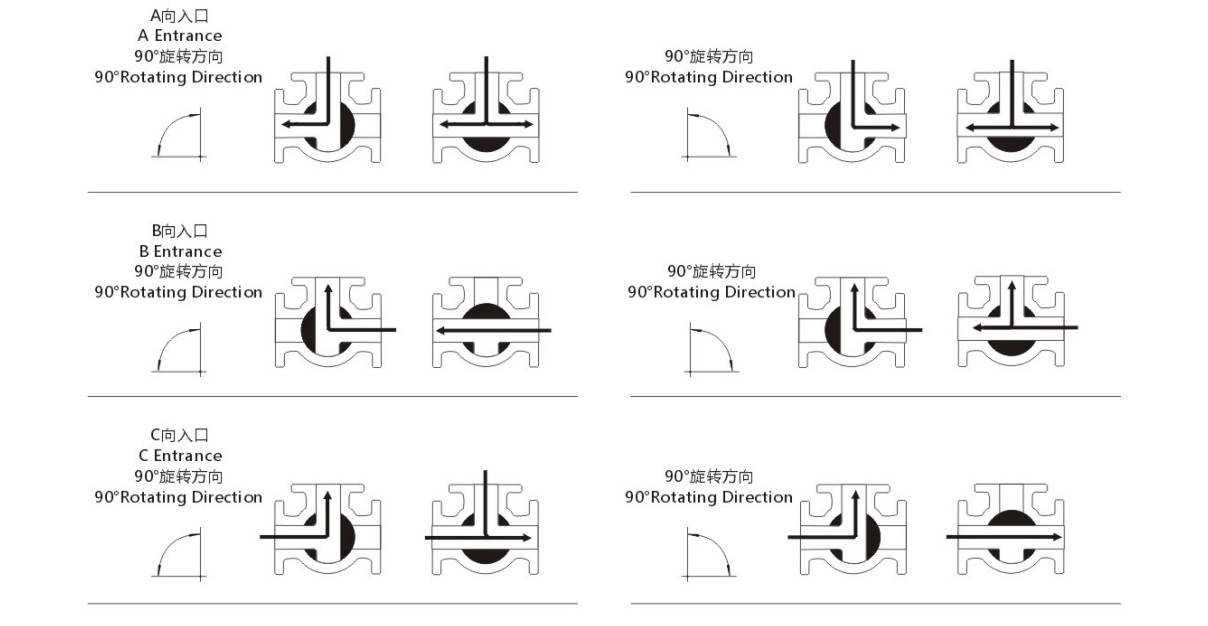
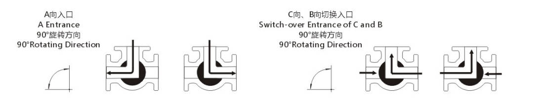
Sketch of Medium Flow-direction of Three-way Ball Valve
Three-way ball valve is used for diffluence or confluent circulation with two-side or four-side valve base embodying multiple channels. All the channels can be used as entrance, with no leakage. The three-way can be made to L-shaped channel or T-shaped channel.
T-shaped Passage
L-shaped Passage
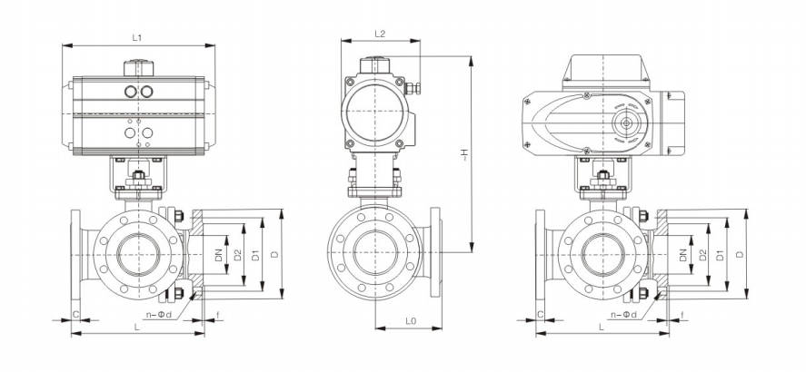
Main Outline and Connecting Flange Size
| DN | in | L | L0 | L1 | L2 | ~H | D | D1 | D2 | C | f | n-Φd | Pneumatic Actuator Model | Electric Actuator Models |
|---|
| 15 | 1/2 | 150 | 72 | 145/169 | 75/84 | 204/235 | 95 | 65 | 46 | 14 | 2 | 4-Φ14 | AT052DR / AT063SC | ZT-05 |
| 20 | 3/4 | 160 | 80 | 169/201 | 84/98 | 240/252 | 105 | 75 | 56 | 16 | 2 | 4-Φ14 | AT063DR / AT075SC | ZT-10 |
| 25 | 1 | 180 | 90 | 201/209 | 98/108 | 257/265 | 115 | 85 | 65 | 16 | 2 | 4-Φ14 | AT075DR / AT083SC | ZT-10 |
| 32 | 1 1/4 | 200 | 100 | 201/242 | 98/120 | 277/312 | 140 | 100 | 76 | 18 | 3 | 4-Φ18 | AT075DR / AT092SC | ZT-10 |
| 40 | 1 1/2 | 220 | 110 | 209/275 | 108/132 | 292/317 | 150 | 110 | 84 | 18 | 3 | 4-Φ18 | AT083DR / AT105SC | ZT-10 |
| 50 | 2 | 240 | 120 | 242/332 | 120/148 | 325/347 | 165 | 125 | 99 | 20 | 3 | 4-Φ18 | AT092DR / AT125SC | ZT-15 |
| 65 | 2 1/2 | 260 | 130 | 275/385 | 132/165 | 357/389 | 185 | 145 | 118 | 20 | 3 | 4-Φ18 | AT105DR / AT140SC | ZT-50 |
| 80 | 3 | 280 | 140 | 332/385 | 148/165 | 368/400 | 200 | 160 | 132 | 20 | 3 | 8-Φ18 | AT125DR / AT140SC | ZT-50 |
| 100 | 4 | 320 | 160 | 385/507 | 165/215 | 410/498 | 220 | 180 | 156 | 22 | 3 | 8-Φ18 | AT140DR / AT190SC | ZT-100 |
| 125 | 5 | 380 | 190 | 450/562 | 188/235 | 470/538 | 250 | 210 | 184 | 22 | 3 | 8-Φ18 | AT160DR / AT210SC | ZT-100 |
| 150 | 6 | 440 | 220 | 507/646 | 215/272 | 556/591 | 285 | 240 | 211 | 24 | 3 | 8-Φ22 | AT190DR / AT240SC | ZT-200 |
| 200 | 8 | 550 | 260 | 562/722 | 235/305 | 648/687 | 340 | 295 | 266 | 24 | 3 | 12-Φ22 | AT210DR / AT270SC | ZT-200 |
2. Fluorine Lined Three Way Ball Valve
Product Description
Fluorine lined three-way ball valve has compact structure which permits use where space constraints are a concern. It is the best choice for corrosive diverter valve applications. High flow capacity with minimal pressure loss through the valve, thereby reducing plant operating costs. Good sealing performance and easy maintenance. Besides applicable for gas and liquid, it works better for
Technique Standard
| Follow The Rules | Standard |
|---|
| Design and Manufacture | GB/T 12237 |
| The Length of The Structure | GB/T 12221 LED-12-02 |
| Flange Dimensions | HG 20592-2009, GB 91131-26 |
| Pressure Test | GB/T 13927 |
| Mark | GB/T 12220 |
| Supply | GB/T 12252 |
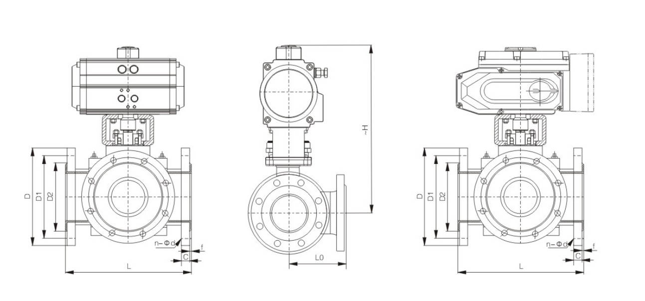
Main Outline and Connecting Flange Size
| DN | L | L0 | D | D1 | D2 | C | f | ~H (PN10) | n-Φd | Double Acting | Single Acting | Electric Actuator Models |
|---|
| 15 | 150 | 75 | 95 | 65 | 40 | 12 | 2 | 204/235 | 4-Φ14 | AT52DR | AT63SC | ZT-05 |
| 20 | 150 | 75 | 105 | 75 | 45 | 14 | 2 | 209/240 | 4-Φ14 | AT63DR | AT75SC | ZT-05 |
| 25 | 180 | 90 | 115 | 85 | 65 | 14 | 2 | 214/265 | 4-Φ14 | AT63DR | AT83SC | ZT-05 |
| 32 | 200 | 100 | 140 | 100 | 78 | 16 | 2 | 269/287 | 4-Φ18 | AT75DR | AT92SC | ZT-10 |
| 40 | 220 | 110 | 150 | 110 | 85 | 16 | 3 | 282/292 | 4-Φ18 | AT75DR | AT105SC | ZT-10 |
| 50 | 240 | 120 | 165 | 125 | 100 | 16 | 3 | 290/325 | 4-Φ18 | AT92DR | AT105SC | ZT-10 |
| 65 | 260 | 130 | 185 | 145 | 120 | 18 | 3 | 310/357 | 4(8)-Φ18 | AT105DR | AT125SC | ZT-10 |
| 80 | 280 | 140 | 200 | 160 | 135 | 18 | 3 | 346/368 | 8-Φ18 | AT125DR | AT140SC | ZT-20 |
| 100 | 320 | 160 | 220 | 180 | 155 | 20 | 3 | 418/443 | 8-Φ18 | AT140DR | AT160SC | ZT-50 |
| 125 | 380 | 190 | 250 | 210 | 185 | 22 | 3 | 460/503 | 8-Φ18 | AT160DR | AT190SC | ZT-50 |
| 150 | 440 | 220 | 285 | 240 | 210 | 22 | 3 | 518/563 | 8-Φ23 | AT190DR | AT210SC | ZT-100 |
| 200 | 550 | 275 | 340 | 295 | 265 | 22 | 3 | 583/618 | 8(12)-Φ23 | AT210DR | AT270SC | ZT-100 |
| 250 | 670 | 335 | 395 | 350 | 320 | 24 | 3 | 663/698 | 12-Φ23 | AT270DR | AT350SC | ZT-200 |
| 300 | 720 | 360 | 445 | 400 | 368 | 26 | 4 | 763/798 | 12-Φ23 | AT300DR | AT400SC | ZT-200 |
3.Threaded Three Way Ball Valve
Technique Standard
| Design Basis | GB Standard | ANSI Standard |
|---|
| Design Standard | GB/T 12237 | ANSI B16.34 |
| Connecting Flange Size | GB/T 9113, JB/T 79 | ANSI B16.5 |
| Test & Inspection | JB/T 9092 | API 598 |
Form of Main Parts Materials
| Name of Parts | Material |
|---|
| Connector | Stainless Steel CF8, CF8M, CF3, CF3M |
| Seat | PTFE, Nylon, PPL |
| Ball | Stainless Steel 304, 304L, 316, 316L |
| Gasket | PTFE |
| Body | Stainless Steel CF8, CF8M, CF3, CF3 |
| Screw | Stainless Steel 304 |
| Stem | Stainless Steel 304, 304L, 316, 316L |
| Gasket | Stainless Steel 304, 316L |
| Packing | PTFE |
| Gland | Stainless Steel 304, 316 |
| Connecting Yoke | Stainless Steel CF8 |
| Connecting Set | Stainless Steel 304 |
| Screw | Stainless Steel 304 |
| Pneumatic Device | AT Series |
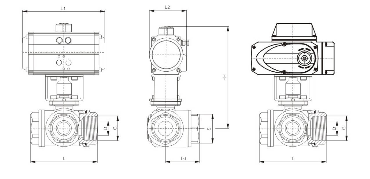
Main Outline and Connecting Flange Size
| DN | in | D | G | L | L0 | L1 | L2 | ~H | S | Pneumatic Actuator Model | Electric Actuator Model |
|---|
| 15 | 1/2 | 10 | 1/2" | 68 | 34 | 145/169 | 75/84 | 177/208 | 26 | AT052DR / AT063SC | ZT-05 |
| 20 | 3/4 | 15 | 3/4" | 78 | 39 | 145/169 | 75/84 | 180/211 | 32 | AT052DR / AT063SC | ZT-10 |
| 25 | 1 | 20 | 1" | 86 | 43 | 169/201 | 84/98 | 199/227 | 38 | AT063DR / AT075SC | ZT-10 |
| 32 | 1 1/4 | 25 | 1 1/4" | 111 | 55.5 | 201/209 | 98/108 | 231/251 | 49 | AT075DR / AT083SC | ZT-10 |
| 40 | 1 1/2 | 32 | 1 1/2" | 126 | 63 | 209/242 | 108/120 | 235/265 | 56 | AT083DR / AT092SC | ZT-15 |
| 50 | 2 | 38 | 2" | 143 | 71.5 | 242/275 | 120/132 | 263/298 | 70 | AT092DR / AT105SC | ZT-15 |
Manufacturing Process
Step 1: Order and Design
According to the customer's requirements, confirm the type (L type or T type), diameter, pressure rating, connection method, valve body material and sealing material of the three-way ball valve.
The engineering department completes the drawing design based on the technical parameters and confirms the flow path structure, sealing form and processing dimensions, providing a basis for subsequent production.
Step 2: Forging & Casting
According to the valve specifications and material requirements, forgings or castings are selected as the blanks for the main components such as the valve body and valve cover.
After forging or casting, the blanks are subjected to sand removal, edge cutting, grinding, and preliminary size inspection and appearance inspection to ensure there are no cracks, shrinkage cavities, or other defects.
Step 3: Machining
Precision mechanical processing is carried out on key components such as the valve body, valve ball, valve stem, and valve seat installation positions.
The main processing contents of the valve body include the flow channel, flange end face, threaded hole, and sealing surface; while the valve ball mainly focuses on processing the channel hole, spherical surface, and mating dimensions.
After processing, dimensional inspection is conducted to ensure assembly accuracy and sealing performance.
Step 4: Assembly
The processed valve bodies, valve balls, valve rods, valve seats, sealing rings, gaskets and actuating components should be assembled according to the process requirements.
During the assembly process, special attention should be paid to the internal flow direction of the three-way ball valve to ensure the correct L-shaped or T-shaped flow path direction, and check whether the opening and closing is flexible.
Step 5: Testing & Quality Assurance
After assembly, strength tests, sealing tests and operation tests are conducted.
The main checks include the pressure-bearing performance of the valve body, the sealing effect of each channel, and whether the torque for valve opening and closing meets the standard requirements.
After passing the tests, the quality inspectors will conduct the final inspection and make product traceability records.
Step 6: Painting and Finishing
After passing the test, the valves undergo surface cleaning, rust prevention treatment and painting.
Subsequently, nameplates and protective covers are installed, and final packaging is carried out.
Before shipment, the finished products are rechecked for model, specification and appearance to ensure they meet the customer's requirements.
Applications
- In the petrochemical industry: used in key process sections such as crude oil diversion and catalyst injection.
- Water treatment system: Achieves water treatment processes such as backwashing and multi-media filtration.
- Thermal pipeline network: Performs flow regulation and heat distribution in the steam distribution system
These valves are widely used in:
Agriculture and Irrigation
Factory Environment
Why Choose Us
Superior Quality

Our valves are manufactured using premium materials and undergo rigorous quality testing to ensure reliable performance in demanding industrial applications.
Advanced Technology

Equipped with state-of-the-art CNC machining centers and precision manufacturing equipment, we deliver valves with exceptional accuracy and consistency.
Competitive Pricing

Through optimized manufacturing processes and bulk material procurement, we offer high-quality valves at competitive prices without compromising on quality.
Expert Support

Our experienced technical team provides comprehensive support from product selection to after-sales service, ensuring optimal valve performance for your specific application.