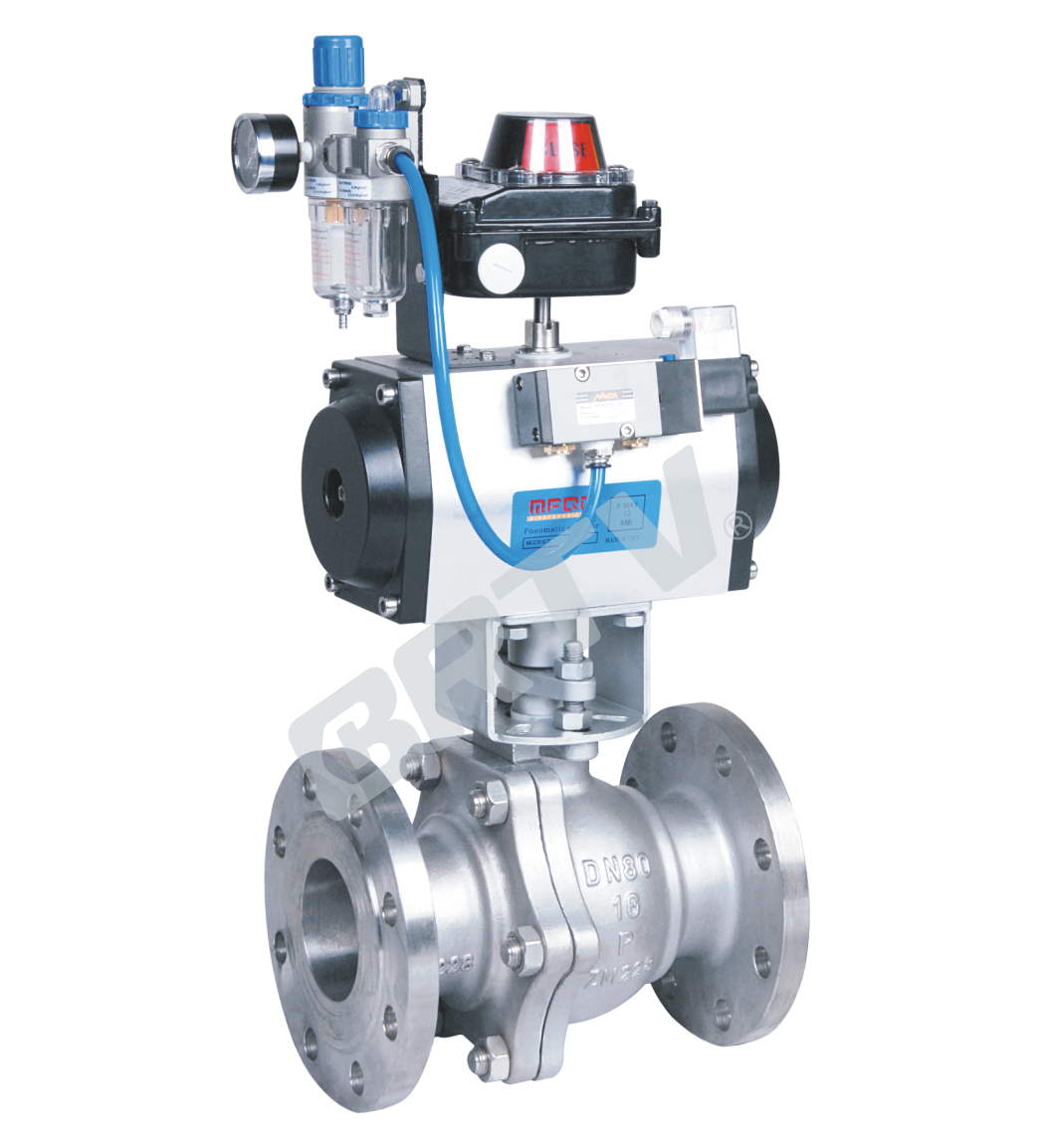
Structure Features
It's mainly used for oil and natural gas storage and transportation, the chemical industry, metallurgy, paper making, food, shipbuilding and other industries to do the opening and closing control of media devices, coupled with pneumatic or electrical device can also be achieved remotely, bail operator safety.
Feature
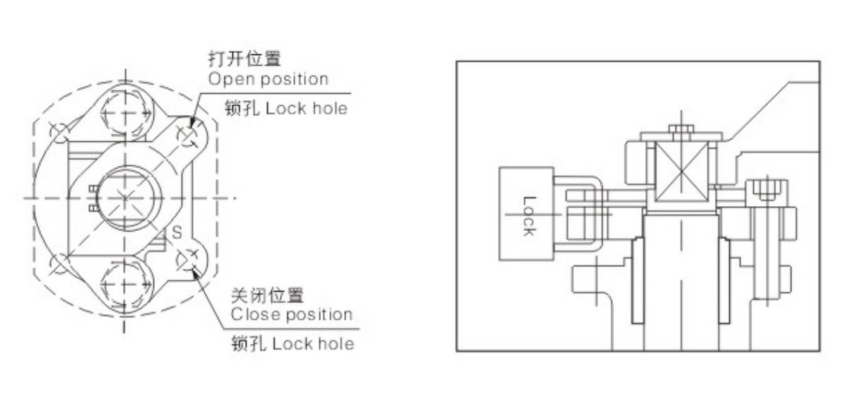
(1).Locking, and limit device to prevent misuse of the valve, the valve can be equipped with a lock limit institutions, especially in the field or for the installation process does not allow to open or close the valve, causing security to prevent misuse of others accident, the valve lock is necessary;
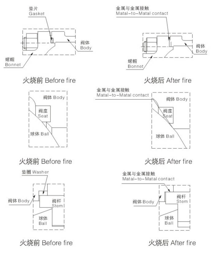
(2).Fire safe, the a fire occurs, when the non-metallic materials of the valve seat and seal damaged at high temperatures, a specially designed metal to metal secondary seal structure, effectively prevent the media a lot of leakage;
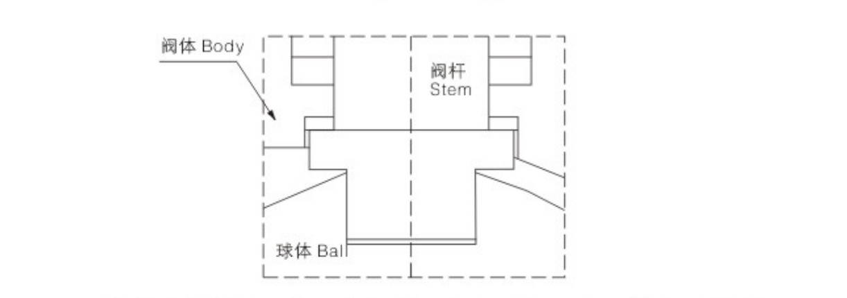
(3).Anti-blow out stem design, stem the use of downloading structure, preventing the abnormal increase as intraluminal pressure forced Blow Out the accident; PTFE thrust washers to ensure smooth between the stem and valve operation;
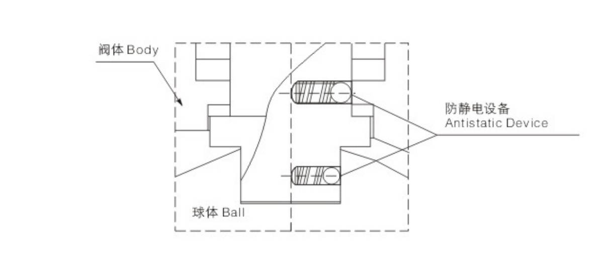
(4).Anti-static design, to ensure that working conditions in the explosive on the safe use;
(5).Body cavity pressure relief design to ensure reliable sealing valve, and extending its life;
1. Floating Ball Valve of GB Standard
Seat Seal Material Temperature Rating
| Code | Material | Applicable Temperature (°C) |
|---|
| F | Reinforced Polytetrafluoroethylene (PTFE) | -40 ~ 180 |
| P | Para-position Polyphenylene | -40 ~ 260 |
| N | Nylon | -20 ~ 80 |
| Y | Hard Alloy | -40 ~ 425 |
Attachment Option
According to different control requirements, the following accessories can be selected:
Shut-off Type Accessories:
Single solenoid valve, double solenoid valve, limit switch, position feedback device, etc.
Control Type Accessories:
Electro-pneumatic positioner, pneumatic positioner, electro-pneumatic converter.
Air Supply Treatment Accessories:
Air filter regulator and air source treatment unit, including: air filter (F), pressure regulator (R), and lubricator (L).
Manual Mechanism:
ZTSD Series.
Technique Standard
| Design Basis | GB Standard |
|---|
| Design Standard | GB/T 12237 |
| Face to Face Dimension | GB/T 12221 |
| Connecting Flange Size | GB/T 9113, JB/T 79 |
| Test & Inspection | GB/T 13927, JB/T 9092 |
Form of Main Parts Materials
| Name of Parts | C | P | RL |
|---|
| Right Valve | WCB | ZG1Cr18Ni9Ti | ZG1Cr18Ni12Mo2Ti |
| Nut | 35 | 06Cr19Ni10 | 06Cr19Ni10 |
| Gasket | PTFE, Graphite metal composite pad | PTFE, Graphite metal composite pad | PTFE, Graphite metal composite pad |
| Screw | 35 | 06Cr19Ni10 | 06Cr19Ni10 |
| Body | WCB | ZG1Cr18Ni9Ti | ZG1Cr18Ni12Mo2Ti |
| Seat | PTFE, Nylon, PPL, Hard Alloy | PTFE, Nylon, PPL, Hard Alloy | PTFE, Nylon, PPL, Hard Alloy |
| Ball | 1Cr18Ni9Ti | 06Cr19Ni10 | 1Cr18Ni12Mo2Ti |
| Stem | 1Cr13 | 06Cr19Ni10 | 1Cr18Ni12Mo2Ti |
| Gasket | 1Cr18Ni9Ti | 06Cr19Ni10 | 1Cr18Ni12Mo2Ti |
| Packing | PTFE, Flexible Graphite | PTFE, Flexible Graphite | PTFE, Flexible Graphite |
| Bushing | PTFE, Composite Bearings | PTFE, Composite Bearings | PTFE, Composite Bearings |
| Gland | WCB | ZG1Cr18Ni9Ti | ZG1Cr18Ni12Mo2Ti |
| Screw | 35 | 06Cr19Ni10 | 06Cr19Ni10 |
| Screw | 35 | 06Cr19Ni10 | 06Cr19Ni10 |
| Connecting Yoke | 35 | 06Cr19Ni10 | 06Cr19Ni10 |
| Screw | 35 | 06Cr19Ni10 | 06Cr19Ni10 |
| Connecting Set | 35 | 2Cr13 | 06Cr19Ni10 |
| Pneumatic Device | AT Series, AW Series, BW Series | AT Series, AW Series, BW Series | AT Series, AW Series, BW Series |
| Location Indicator | Plastic | Plastic | Plastic |
Pneumatic Ball Valve Standard Specification
| Model | ZTQ641F (N, P, H, Y) |
|---|
| Bore | DN15 ~ 300 mm |
| Pressure | 1.6, 2.5, 4.0, 6.4 MPa; 150Lb, 300Lb, 600Lb; 10K, 20K |
| Structure | Floating |
| Dimension Standard | GB Standard, American Standard, Japanese Standard |
| Body Material | Carbon Steel (WCB), Stainless Steel (CF8, CF8M, F3, CF3M) |
| Seat Material | PTFE (F), PPL (P), Nylon (N), Hard Alloy (H, Y) |
| Mode of Action | Double-acting / Single-acting (spring return) pneumatic actuator |
| Control | Switch Type, Adjust Type, Intelligent |
| Selection of Accessories | Solenoid Valve, Locator, Limit Switch, F.R.L. Combination Unit, Manual Device |
Electric Ball Valve Standard Specification
| Model | ZTQ941F (N, P, H, Y) |
|---|
| Bore | DN15 ~ 300 mm |
| Pressure | 1.6, 2.5, 4.0, 6.4 MPa; 150Lb, 300Lb, 600Lb; 10K, 20K |
| Structure | Floating |
| Dimension Standard | GB Standard, American Standard, Japanese Standard |
| Body Material | Carbon Steel (WCB), Stainless Steel (CF8, CF8M, F3, CF3M) |
| Seat Material | PTFE (F), PPL (P), Nylon (N), Hard Alloy (H, Y) |
| Mode of Action | Power on type, Power off type |
| Control | Switch Type, Adjust Type, Intelligent |
| Selection of Accessories | Stroke Switch, Analog Quantity Feedback Module, Electric Control Box |
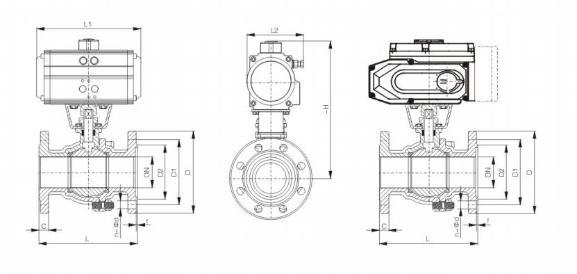
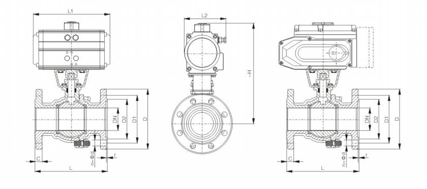
Main Outline and Connecting Flange Size
| DN | L | L1 | L2 | ~H | D | D1 | D2 | C | f | n-Φd | Pneumatic Actuator Model | Electric Actuator Models |
|---|
| 15 | 130 | 145/169 | 75/84 | 204/235 | 95 | 65 | 45 | 14 | 2 | 4-Φ14 | AT052DR/AT063SC | ZT-03 |
| 20 | 140 | 145/169 | 75/84 | 209/240 | 105 | 75 | 55 | 14 | 2 | 4-Φ14 | AT052DR/AT063SC | ZT-03 |
| 25 | 150 | 145/201 | 75/98 | 214/256 | 115 | 85 | 65 | 14 | 2 | 4-Φ14 | AT052DR/AT075SC | ZT-03 |
| 32 | 165 | 169/209 | 84/108 | 257/277 | 135 | 100 | 78 | 16 | 2 | 4-Φ18 | AT063DR/AT083SC | ZT-05 |
| 40 | 180 | 201/242 | 98/120 | 274/292 | 145 | 110 | 85 | 16 | 3 | 4-Φ18 | AT075DR/AT092SC | ZT-10 |
| 50 | 200 | 209/275 | 108/132 | 290/300 | 160 | 125 | 100 | 16 | 3 | 4-Φ18 | AT083DR/AT105SC | ZT-10 |
| 65 | 220 | 242/275 | 120/132 | 310/335 | 180 | 145 | 120 | 18 | 3 | 4-Φ18 | AT092DR/AT105SC | ZT-15 |
| 80 | 250 | 275/332 | 132/148 | 346/368 | 195 | 160 | 135 | 20 | 3 | 8-Φ18 | AT105DR/AT125SC | ZT-20 |
| 100 | 280 | 332/385 | 148/165 | 378/410 | 215 | 180 | 155 | 20 | 3 | 8-Φ18 | AT125DR/AT140SC | ZT-50 |
| 125 | 320 | 385/450 | 165/188 | 425/450 | 245 | 210 | 185 | 22 | 3 | 8-Φ18 | AT140DR/AT160SC | ZT-100 |
| 150 | 360 | 450/562 | 188/215 | 468/531 | 280 | 240 | 210 | 24 | 3 | 8-Φ23 | AT160DR/AT190SC | ZT-100 |
| 200 | 400 | 562/646 | 235/272 | 583/618 | 335 | 295 | 265 | 26 | 3 | 12-Φ23 | AT210DR/AT240SC | ZT-200 |
| 250 | 533 | 562/646 | 235/272 | 762/792 | 405 | 355 | 320 | 30 | 3 | 12-Φ25 | AT240DR/AT300SC | ZMQ-300 |
| 300 | 610 | 646/722 | 272/292 | 792/822 | 460 | 410 | 375 | 30 | 4 | 12-Φ25 | AT300DR/AT400SC | ZMQ-400 |
2. Floating Ball Valve of ANSI Standard
Technique Standard
| Design Basis | API, ANSI Standard |
|---|
| Design Standard | API 6D, ANSI B16.34 |
| Face to Face Dimension | API 6D, ANSI B16.10 |
| Connecting Flange Size | ANSI B16.5 |
| Test & Inspection | API 6D, API 598 |
Form of Main Parts Materials
| Name of Parts | C | P | R |
|---|
| Right Valve | A216-WCB | A351-CF8 | A351-CF8M |
| Nut | A194-2H | A276-304 | A276-316 |
| Gasket | PTFE, Graphite metal composite pad | PTFE, Graphite metal composite pad | PTFE, Graphite metal composite pad |
| Screw | A193-B7 | A276-304 | A276-316 |
| Body | A216-WCB | A351-CF8 | A351-CF8M |
| Seat | PTFE, Nylon, PPL, Hard Alloy | PTFE, Nylon, PPL, Hard Alloy | PTFE, Nylon, PPL, Hard Alloy |
| Ball | A182-F304 | A182-F304 | A182-F316 |
| Stem | A276-410 | A276-304 | A276-316 |
| Gasket | A276-304 | A276-304 | A276-316 |
| Packing | PTFE, Flexible Graphite | PTFE, Flexible Graphite | PTFE, Flexible Graphite |
| Bushing | PTFE, Composite Bearings | PTFE, Composite Bearings | PTFE, Composite Bearings |
| Gland | A216-WCB | A351-CF8 | A351-CF8M |
| Screw | A194-2H | A276-304 | A276-304 |
| Screw | A194-2H | A276-304 | A276-304 |
| Connecting Yoke | A351-CF8 | A351-CF8 | A351-CF8 |
| Screw | A194-2H | A276-304 | A276-304 |
| Connecting Set | A351-CF8 | A351-CF8 | A351-CF8 |
| Pneumatic Device | AT Series, AW Series, BW Series | AT Series, AW Series, BW Series | AT Series, AW Series, BW Series |
| Location Indicator | Plastic | Plastic | Plastic |
Main Outline and Connecting Flange Size
| mm | in | L | L1 | L2 | ~H | D | D1 | D2 | C | f | n-Φd | Pneumatic Actuator Model | Electric Actuator Models |
|---|
| 15 | 1/2 | 108 | 145/169 | 75/84 | 204/235 | 89 | 60.5 | 35 | 12 | 1.6 | 4-Φ16 | AT052DR/AT063SC | ZT-03 |
| 20 | 3/4 | 117 | 145/169 | 75/84 | 209/240 | 99 | 70 | 43 | 13 | 1.6 | 4-Φ16 | AT052DR/AT063SC | ZT-05 |
| 25 | 1 | 127 | 169/201 | 84/98 | 214/256 | 108 | 79.5 | 51 | 14.5 | 1.6 | 4-Φ17 | AT063DR/AT075SC | ZT-05 |
| 32 | 1 1/4 | 140 | 201/209 | 98/108 | 257/277 | 117 | 89 | 64 | 15 | 1.6 | 4-Φ17 | AT075DR/AT083SC | ZT-10 |
| 40 | 1 1/2 | 165 | 209/275 | 108/132 | 274/292 | 127 | 98.5 | 73 | 17.5 | 1.6 | 4-Φ22 | AT083DR/AT105SC | ZT-10 |
| 50 | 2 | 178 | 242/275 | 120/132 | 290/300 | 152 | 120.5 | 92 | 19 | 1.6 | 4-Φ25 | AT092DR/AT105SC | ZT-15 |
| 65 | 2 1/2 | 190 | 275/332 | 132/148 | 310/335 | 178 | 139.5 | 105 | 22.5 | 1.6 | 4-Φ29 | AT105DR/AT125SC | ZT-15 |
| 80 | 3 | 203 | 275/332 | 132/148 | 346/368 | 190 | 152.5 | 127 | 24 | 1.6 | 4-Φ30 | AT105DR/AT125SC | ZT-50 |
| 100 | 4 | 229 | 332/385 | 148/165 | 378/410 | 229 | 190.5 | 157 | 24 | 1.6 | 8-Φ33 | AT125DR/AT140SC | ZT-50 |
| 125 | 5 | 356 | 385/450 | 165/188 | 425/450 | 254 | 216 | 186 | 24 | 1.6 | 8-Φ36 | AT140DR/AT160SC | ZT-100 |
| 150 | 6 | 394 | 507/562 | 215/235 | 468/531 | 279 | 241.5 | 216 | 25.5 | 1.6 | 8-Φ40 | AT190DR/AT210SC | ZT-200 |
| 200 | 8 | 457 | 646/722 | 272/305 | 583/618 | 343 | 298.5 | 270 | 29 | 1.6 | 8-Φ44 | AT240DR/AT270SC | ZMQ-300 |
| mm | in | L | L1 | L2 | ~H | D | D1 | D2 | C | f | n-Φd | Pneumatic Actuator Model | Electric Actuator Models |
|---|
| 15 | 1/2 | 140 | 145/169 | 75/84 | 204/235 | 95 | 65.7 | 35 | 14.5 | 1.6 | 4-Φ16 | AT052DR/AT063SC | ZT-05 |
| 20 | 3/4 | 152 | 145/169 | 75/84 | 209/240 | 117 | 82.5 | 43 | 16 | 1.6 | 4-19 | AT052DR/AT063SC | ZT-05 |
| 25 | 1 | 165 | 201/209 | 98/108 | 214/265 | 124 | 89 | 51 | 17.5 | 1.6 | 4-19 | AT075DR/AT083SC | ZT-10 |
| 32 | 1 1/4 | 178 | 209/242 | 108/120 | 269/287 | 133 | 99 | 64 | 19 | 1.6 | 4-19 | AT083DR/AT092SC | ZT-10 |
| 40 | 1 1/2 | 190 | 242/275 | 120/132 | 282/292 | 156 | 114.5 | 73 | 21 | 1.6 | 4-19 | AT092DR/AT105SC | ZT-15 |
| 50 | 2 | 216 | 275/332 | 132/148 | 290/325 | 165 | 127 | 92 | 22.5 | 1.6 | 4-Φ19 | AT105DR/AT125SC | ZT-20 |
| 65 | 2 1/2 | 241 | 275/332 | 132/148 | 310/357 | 190 | 149 | 105 | 25.5 | 1.6 | 8-19 | AT105DR/AT125SC | ZT-20 |
| 80 | 3 | 283 | 332/385 | 148/165 | 346/368 | 210 | 168.5 | 127 | 29 | 1.6 | 8-22 | AT125DR/AT140SC | ZT-50 |
| 100 | 4 | 305 | 385/450 | 165/188 | 418/443 | 254 | 200 | 157 | 32 | 1.6 | 8-Φ22 | AT140DR/AT160SC | ZT-100 |
| 125 | 5 | 381 | 450/507 | 188/215 | 460/503 | 279 | 235 | 186 | 35 | 1.6 | 8-Φ26 | AT160DR/AT190SC | ZT-100 |
| 150 | 6 | 403 | 562/646 | 235/272 | 518/563 | 318 | 270 | 216 | 37 | 1.6 | 12-Φ26 | AT210DR/AT240SC | ZT-200 |
| 200 | 8 | 502 | 646/722 | 272/305 | 583/618 | 381 | 330 | 270 | 41.5 | 1.6 | 12-29 | AT240DR/AT270SC | ZMQ-400 |
3. Floating Ball Valve of JIS Standard
Technique Standard
| Design Basis | JIS Standard |
|---|
| Design Standard | BS 5351 |
| Face To Face Dimension | JIS B2002 |
| Connecting Flange Size | JIS B2212, B2213, B2214 |
| Test & Inspection | JIS B2003 |
Main Outline and Connecting Flange Size
| Name of Parts | C | P | R |
|---|
| Right Valve | SCPH2 | SCS13 | SCS14 |
| Nut | S35C | SUS304 | SUS304 |
| Gasket | PTFE, Graphite metal composite pad | PTFE, Graphite metal composite pad | PTFE, Graphite metal composite pad |
| Screw | S35C | SUS304 | SUS304 |
| Body | SCPH2 | SCS13 | SCS14 |
| Seat | PTFE, Nylon, PPL, Hard Alloy | PTFE, Nylon, PPL, Hard Alloy | PTFE, Nylon, PPL, Hard Alloy |
| Ball | SUS304 | SUS304 | SUS316 |
| Stem | SUS410 | SUS304 | SUS316 |
| Gasket | SUS304 | SUS304 | SUS316 |
| Packing | PTFE, Flexible Graphite | PTFE, Flexible Graphite | PTFE, Flexible Graphite |
| Bushing | PTFE, Composite Bearings | PTFE, Composite Bearings | PTFE, Composite Bearings |
| Gland | SCPH2 | SCS13 | SCS14 |
| Screw | S35C | SUS304 | SUS304 |
| Screw | S35C | SUS304 | SUS304 |
| Connecting Yoke | SCS13 | SCS13 | SCS13 |
| Screw | S35C | SUS304 | SUS304 |
| Connecting Set | SCS13 | SCS13 | SCS13 |
| Pneumatic Device | AT Series, AW Series, BW Series | AT Series, AW Series, BW Series | AT Series, AW Series, BW Series |
| Location Indicator | Plastic | Plastic | Plastic |
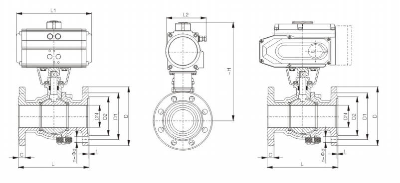
| mm | in | L | L1 | L2 | ~H | D | D1 | D2 | C | f | n-Φd | Pneumatic Actuator Model | Electric Actuator Models |
|---|
| 15 | 1/2 | 108 | 145/169 | 75/84 | 204/235 | 95 | 70 | 51 | 12 | 1 | 4-Φ15 | AT052DR/AT063SC | ZT-03 |
| 20 | 3/4 | 117 | 145/169 | 75/84 | 209/240 | 100 | 75 | 56 | 14 | 1 | 4-15 | AT052DR/AT063SC | ZT-03 |
| 25 | 1 | 127 | 169/201 | 84/98 | 214/256 | 125 | 90 | 67 | 14 | 1 | 4-19 | AT063DR/AT075SC | ZT-05 |
| 32 | 1 1/4 | 140 | 201/209 | 98/108 | 257/277 | 135 | 100 | 76 | 16 | 2 | 4-19 | AT075DR/AT083SC | ZT-10 |
| 40 | 1 1/2 | 165 | 209/275 | 108/132 | 274/292 | 140 | 105 | 81 | 16 | 2 | 4-19 | AT083DR/AT105SC | ZT-10 |
| 50 | 2 | 178 | 242/275 | 120/132 | 290/300 | 155 | 120 | 96 | 16 | 2 | 4-Φ19 | AT092DR/AT105SC | ZT-15 |
| 65 | 2 1/2 | 190 | 275/332 | 132/148 | 310/335 | 175 | 140 | 116 | 18 | 2 | 4-19 | AT105DR/AT125SC | ZT-20 |
| 80 | 3 | 203 | 275/332 | 132/148 | 346/368 | 185 | 150 | 126 | 18 | 2 | 8-19 | AT105DR/AT125SC | ZT-20 |
| 100 | 4 | 229 | 332/385 | 148/165 | 378/410 | 210 | 175 | 151 | 18 | 2 | 8-19 | AT125DR/AT140SC | ZT-50 |
| 125 | 5 | 356 | 385/450 | 165/188 | 425/450 | 250 | 210 | 182 | 20 | 2 | 8-Φ23 | AT140DR/AT160SC | ZT-100 |
| 150 | 6 | 394 | 450/562 | 188/235 | 468/531 | 280 | 240 | 212 | 22 | 2 | 8-23 | AT160DR/AT210SC | ZT-100 |
| 200 | 8 | 457 | 562/646 | 235/272 | 583/618 | 330 | 290 | 262 | 22 | 2 | 12-23 | AT210DR/AT240SC | ZT-200 |
4.Cast Steel Floating Ball Valve
Design Construction
(1). Design Standard:API 6D、BS5351、ASME B16.34、GB/T12237
(2). Face to Face:ASME B16.10、GB/T12221
(3). Flange size:ASME B16.5、GB/T9113
(4). Test & Inspection:API 598、JB/T9092
Notes: The sizes of serial valve connecting flange and butt-weldingl terminal can be designed according to customer's requirement.
Product Model
Q(3、6、7、8、9)4(6)1F(Y、N、P)
Major Parts Material Form
| No. | Accessory Name | Carbon Steel Series | Stainless Steel Series | Cryogenic Steel Series |
|---|
| 1 | Bonnet | A216 WCB | A351-CF8, CF8M, CF3, CF3M | A352 LCB, LCC |
| 2 | Nut | A194 2H | A194 8M | A194 4 |
| 3 | Gasket | Flexible Graphite + Stainless Steel | Flexible Graphite + Stainless Steel | Flexible Graphite + Stainless Steel |
| 4 | Stud | A193-B7 | A193-B8 | A320 L7M |
| 5 | Body | A216 WCB | A351-CF8, CF8M, CF3, CF3M | A352 LCB, LCC |
| 6 | Seat | PTFE, RPTFE, Sintering Carbon Fibre, Metal+Rubber | PTFE, RPTFE, Sintering Carbon Fibre, Metal+Rubber | PTFE, RPTFE, Sintering Carbon Fibre, Metal+Rubber |
| 7 | Ball* | A105+HCr/ENP | A182 F304, A182 F316 | A350 LF2, A350 LF3+ENP |
| 8 | Stem** | A182 F6a | A182 F304, 316 | A182 F6a |
| 9 | Gasket | A182 F6a | | A182 F6a |
| 10 | Packing Gasket | Flexible Graphite, PTFE | Flexible Graphite, PTFE | Flexible Graphite, PTFE |
| 11 | Gland | A216 WCB | A351 CF8, CF8M | A351 CF8 |
| 12 | Screw Nail | A193 B7 | A193 B8, B8M | A320 L7 |
| 13 | Locating Piece | GB/T 700 Q235A+Zn(Cr) | GB/T 700 Q235A+Zn(Cr) | GB/T 700 Q235A+Zn(Cr) |
| 14 | Ring | A216 WCB | A216 WCB | A216 WCB |
| 15 | Wrench | GB/T 1222 65Mn | GB/T 1222 65Mn | GB/T 1222 65Mn |
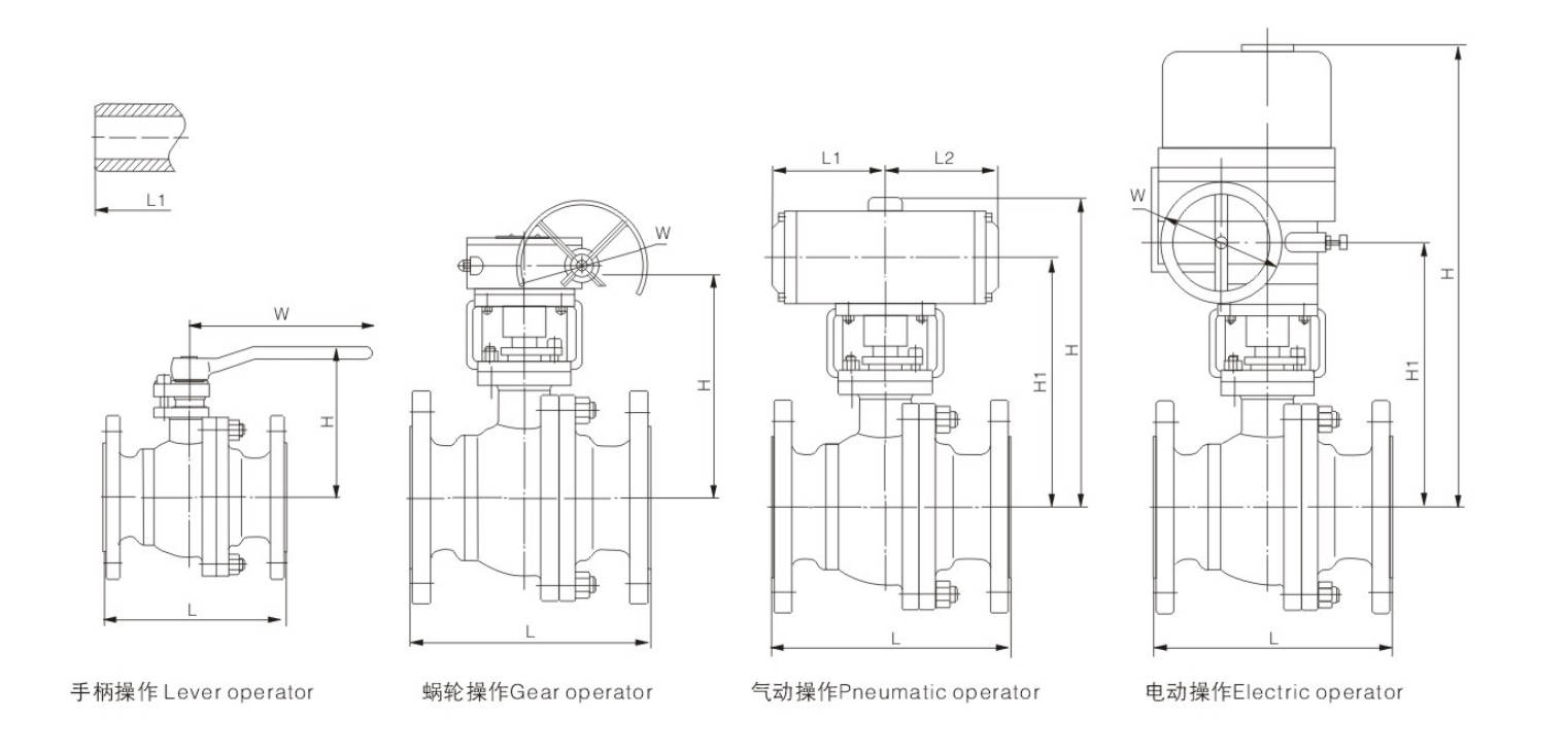
Main Size of Outside & Weight
PN1.6MPa CLASS150
| Item | Type | 15 | 20 | 25 | 40 | 50 | 65 | 80 | 100 | 125 | 150 | 200 |
|---|
| DN (mm) | | 15 | 20 | 25 | 40 | 50 | 65 | 80 | 100 | 125 | 150 | 200 |
| NPS (in) | | 1/2 | 3/4 | 1 | 1½ | 2 | 2½ | 3 | 4 | 5 | 6 | 8 |
| L | RF | 108 | 117 | 127 | 165 | 178 | 190 | 203 | 229 | 356 | 394 | 457 |
| Lo | BW | 140 | 152 | 165 | 190 | 216 | 241 | 283 | 305 | 381 | 457 | 521 |
| Hand-operated | M | 59 | 63 | 75 | 95 | 107 | 142 | 152 | 178 | 252 | 272 | 342 |
| Hand-operated | MO | 130 | 130 | 160 | 230 | 230 | 400 | 400 | 650 | 1050 | 1050 | 1410 |
| Worm Gear | B | / | / | / | / | / | / | / | / | / | 292 | 398 |
| Worm Gear | B0 | / | / | / | / | / | / | / | / | / | 400 | 600 |
| Worm Gear | B1 | / | / | / | / | / | / | / | / | / | 350 | 350 |
| Worm Gear | B2 | / | / | / | / | / | / | / | / | / | 115.5 | 115.5 |
| Pneumatic Operated | A | 200 | 204 | 257 | 264 | 340 | 370 | 389 | 594 | 646 | 646 | 781 |
| Pneumatic Operated | A1 | 122 | 126 | 162 | 169 | 209 | 239 | 258 | 337 | 437 | 437 | 537 |
| Pneumatic Operated | A2 | 326 | 326 | 347 | 420 | 426 | 426 | 590 | 523 | 610 | 610 | 885 |
| Pneumatic Operated | A3 | 136 | 136 | 181 | 181 | 257 | 257 | 257 | 287 | 378 | 378 | 530 |
| Electric Driving | D | / | / | / | / | 472 | 486 | 579 | 595 | 650 | 739 | 799 |
| Electric Driving | D1 | / | / | / | / | 377 | 391 | 484 | 500 | 500 | 589 | 649 |
| Electric Driving | D0 | / | / | / | / | 190 | 190 | 190 | 190 | 400 | 400 | 400 |
| Weight (kg) | Manual | 2.5 | 3 | 5 | 7 | 10 | 15 | 19 | 33 | 58 | 93 | 160 |
| Weight (kg) | Pneumatic | 10 | 15.7 | 19.5 | 42.8 | 46.9 | 50.5 | 70 | 92.7 | 160.7 | 183.5 | 276 |
| Weight (kg) | Electric | / | / | / | / | 32 | 35.6 | 44 | 55 | 93 | 128 | 195 |
PN2.5/4.0MPa CLASS 300
| Item | Type | 15 | 20 | 25 | 40 | 50 | 65 | 80 | 100 | 125 | 150 | 200 |
|---|
| DN (mm) | | 15 | 20 | 25 | 40 | 50 | 65 | 80 | 100 | 125 | 150 | 200 |
| NPS (in) | | 1/2 | 3/4 | 1 | 1½ | 2 | 2½ | 3 | 4 | 5 | 6 | 8 |
| L | RF | 140 | 152 | 165 | 190 | 216 | 241 | 283 | 305 | 381 | 403 | 502 |
| Lo | BW | 140 | 152 | 165 | 190 | 216 | 241 | 283 | 305 | 381 | 457 | 521 |
| Hand-operated | M | 59 | 63 | 75 | 95 | 107 | 142 | 152 | 178 | 252 | 272 | 342 |
| Hand-operated | MO | 130 | 130 | 160 | 230 | 230 | 400 | 400 | 650 | 1050 | 1050 | 1410 |
| Worm Gear | B | / | / | / | / | / | / | / | / | / | 292 | 398 |
| Worm Gear | B0 | / | / | / | / | / | / | / | / | / | 400 | 600 |
| Worm Gear | B1 | / | / | / | / | / | / | / | / | / | 350 | 421 |
| Worm Gear | B2 | / | / | / | / | / | / | / | / | / | 115.5 | 171 |
| Pneumatic / Hydraulic Operated | A | 200 | 204 | 257 | 264 | 340 | 379 | 452 | 594 | 646 | 744 | 920 |
| Pneumatic / Hydraulic Operated | A1 | 122 | 126 | 162 | 169 | 209 | 248 | 295 | 375 | 437 | 500 | 615 |
| Pneumatic / Hydraulic Operated | A3 | 326 | 326 | 347 | 420 | 426 | 426 | 590 | 523 | 610 | 610 | 885 |
| Pneumatic / Hydraulic Operated | A4 | 136 | 136 | 181 | 181 | 257 | 257 | 257 | 287 | 378 | 378 | 530 |
| Electric Driving | D | / | / | / | / | 472 | 486 | 579 | 595 | 650 | 739 | 799 |
| Electric Driving | D1 | / | / | / | / | 377 | 391 | 484 | 500 | 500 | 589 | 649 |
| Electric Driving | D0 | / | / | / | / | 190 | 190 | 190 | 190 | 400 | 400 | 400 |
| Weight (kg) | Manual | 3 | 4 | 6 | 11 | 15 | 24 | 30 | 55 | 81 | 118 | 200 |
| Weight (kg) | Pneumatic | 10 | 15.7 | 20 | 40.9 | 43.9 | 51.9 | 68 | 99.4 | 177.5 | 207.5 | 381 |
| Weight (kg) | Electric | / | / | / | / | 29 | 37 | 42 | 77 | 116 | 143 | 235 |
PN6.4/10.0MPa CLASS 600
| Item | Type | 15 | 20 | 25 | 40 | 50 | 65 | 80 | 100 |
|---|
| DN (mm) | | 15 | 20 | 25 | 40 | 50 | 65 | 80 | 100 |
| NPS (in) | | 1/2 | 3/4 | 1 | 1½ | 2 | 2½ | 3 | 4 |
| L | RF | 165 | 190 | 216 | 241 | 292 | 330 | 356 | 406 (432) |
| Lo | BW | 165 | 190 | 216 | 241 | 292 | 330 | 356 | 406 (432) |
| Hand-operated | M | 59 | 63 | 75 | 95 | 142 | 154 | 184 | 209 |
| Hand-operated | MO | 160 | 160 | 230 | 400 | 400 | 650 | 650 | 1050 |
| Worm Gear | B | / | / | / | / | / | / | 292 | 398 |
| Worm Gear | B0 | / | / | / | / | / | / | 400 | 600 |
| Worm Gear | B1 | / | / | / | / | / | / | 350 | 421 |
| Worm Gear | B2 | / | / | / | / | / | / | 115.5 | 171 |
| Pneumatic / Hydraulic Operated | A1 | 122 | 145 | 146 | 169 | 209 | 248 | 295 | 375 |
| Pneumatic / Hydraulic Operated | A3 | 283 | 283 | 283 | 350 | 590 | 590 | 523 | 610 |
| Pneumatic / Hydraulic Operated | A4 | 136 | 136 | 181 | 181 | 257 | 257 | 287 | 378 |
| Electric Driving | D | / | / | / | / | 472 | 599 | 599 | 632 |
| Electric Driving | D1 | / | / | / | / | 377 | 491 | 449 | 472 |
| Electric Driving | D0 | / | / | / | / | 190 | 190 | 190 | 190 |
| Weight (kg) | Manual | 8 | 11 | 15 | 19 | 25 | 32 | 48 | 76 |
| Weight (kg) | Pneumatic | 17.2 | 21 | 24 | 32 | 68 | 75 | 101.3 | 177.5 |
| Weight (kg) | Electric | / | / | / | / | 60 | 67 | 83 | 111 |
5.Forged Steel Floating Ball Valve
Design Construction
-
Design Standard:API 6D、BS5351、ASME B16.34、GB/T12237
-
Face to Face:ASME B16.10、GB/T12221
-
Flange size:ASME B16.5、GB/T9113
-
Test & Inspection:API 598、JB/T9092
Notes: The sizes of serial valve connecting flange and butt-weldingl terminal can be designed according to customer's requirement.
Product Model
Q(3、6、7、8、9)4(6)1F(Y、N、P)
Products Performance Specification
| Performance Specification | 1.6 MPa | 2.5 MPa | 4.0 MPa | 6.4 MPa | 10.0 MPa | Class 150 | Class 300 | Class 400 | Class 600 |
|---|
| Shell Test (MPa) | 2.4 | 3.75 | 6.0 | 9.6 | 15.0 | 2.93 | 7.58 | 10.0 | 15.0 |
| Seal Test (MPa) | 1.76 | 2.75 | 4.4 | 7.04 | 11.0 | 2.07 | 5.52 | 7.31 | 11.03 |
| Air Test | - | - | - | - | - | - | - | - | 0.6 MPa |
| Applicable Temperature | -196°C ~ 550°C | | | | | | | | |
| Applicable Medium | Water, Steam, Petroleum, LPG, Natural Gas, etc. | | | | | | | | |
Major Parts Materials Form
| No. | Accessory Name | ASTM Material | No. | Accessory Name | ASTM Material |
|---|
| 1 | Gasket | Flexible graphite + stainless steel | 9 | Gasket | PTFE |
| 2 | Seat | PTFE | 10 | Packing Seat | A276-410 |
| 3 | Bonnet | A105 | 11 | Packing | Flexible graphite |
| 4 | Nut | A194-2H | 12 | Gland | A216-WCB |
| 5 | Stud | A193-B7 | 13 | Bolt | A193-B7 |
| 6 | Body | A105 | 14 | Locating Piece | Carbon steel |
| 7 | Ball | A105 + ENP | 15 | Ring | AISI 1566 |
| 8 | Stem | A182-F6a | 16 | Wrench | A47-667 32510 |
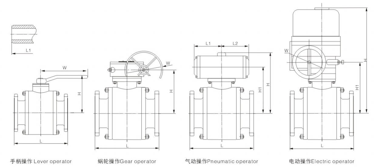
Main Size of Outside & Weight
PN1.6MPa CLASS 150
| Item | Type | 15 | 20 | 25 | 40 | 50 | 65 | 80 | 100 | 125 | 150 | 200 |
|---|
| Flange | L | 108 | 117 | 127 | 165 | 178 | 190 | 203 | 229 | 356 | 394 | 457 |
| Butt Welding | L1 | 140 | 152 | 165 | 190 | 216 | 241 | 282 | 305 | 381 | 403 | 419 |
| Hand-operated | H | 73 | 78 | 86 | 102 | 130 | 142 | 191 | 200 | 226 | 242 | 285 |
| Hand-operated | W | 130 | 130 | 160 | 180 | 230 | 400 | 400 | 460 | 750 | 750 | 900 |
| Hand-operated | Kg | 3 | 4 | 6 | 12 | 15 | 19 | 22 | 46 | 65 | 85 | 127 |
| Worm Gear | H | - | - | - | - | - | - | - | - | - | 260 | 300 |
| Worm Gear | W | - | - | - | - | - | - | - | - | - | 400 | 600 |
| Worm Gear | Type | - | - | - | - | - | - | - | - | - | A | B |
| Worm Gear | Kg | - | - | - | - | - | - | - | - | - | 110 | 175 |
| Pneumatic | H | 203 | 234 | 242 | 326 | 354 | 366 | 415 | 485 | 607 | 623 | 742 |
| Pneumatic | H1 | 125 | 139 | 147 | 195 | 223 | 235 | 284 | 328 | 398 | 414 | 498 |
| Pneumatic | L2 | 326 | 326 | 347 | 420 | 426 | 426 | 590 | 523 | 610 | 610 | 885 |
| Pneumatic | L3 | 136 | 136 | 181 | 181 | 257 | 257 | 257 | 287 | 378 | 378 | 530 |
| Pneumatic | Type | AG06 | AG09 | AG09 | AG13 | AG13 | AG13 | AG13 | AW13 | AW17 | AW17 | AW20 |
| Pneumatic | Kg | 6.1 | 6.3 | 8.1 | 14.1 | 16.6 | 38.0 | 42.1 | 53.0 | 93.5 | 105.2 | 207.8 |
| Electric | H | - | - | - | - | 432 | 443 | 454 | 493 | 574 | 646 | 678 |
| Electric | H1 | - | - | - | - | 337 | 348 | 359 | 398 | 424 | 496 | 528 |
| Electric | W | - | - | - | - | 190 | 190 | 190 | 190 | 400 | 400 | 400 |
| Electric | Type | - | - | - | - | Q60-1 | Q60-1 | Q60-1 | Q60-1 | Q120-1 | Q120-1 | Q120-1 |
| Electric | Kg | - | - | - | - | 23 | 25 | 60 | 75 | 97 | 162 | 226 |
PN2.5/4.0MPa CLASS 300
| Item | Type | 15 | 20 | 25 | 40 | 50 | 65 | 80 | 100 | 125 | 150 | 200 |
|---|
| Flange | L | 140 | 152 | 165 | 190 | 216 | 241 | 282 | 305 | 381 | 403 | 502 |
| Butt Welding | L1 | 140 | 152 | 165 | 190 | 216 | 241 | 282 | 305 | 381 | 403 | 502 |
| Hand-operated | H | 73 | 80 | 86 | 102 | 136 | 164 | 191 | 223 | 240 | 253 | 307 |
| Hand-operated | W | 140 | 140 | 180 | 230 | 240 | 400 | 400 | 750 | 750 | 900 | 1000 |
| Hand-operated | Kg | 6 | 6.8 | 11.2 | 18.3 | 32 | 38 | 78 | 85 | 102 | 125 | 125 |
| Worm Gear | H | - | - | - | - | - | - | - | - | - | 325 | 387 |
| Worm Gear | W | - | - | - | - | - | - | - | - | - | 400 | 600 |
| Worm Gear | Type | - | - | - | - | - | - | - | - | - | A | B |
| Worm Gear | Kg | - | - | - | - | - | - | - | - | - | 148 | 196 |
| Pneumatic | H | 204 | 236 | 242 | 326 | 359 | 388 | 415 | 508 | 621 | 675 | 824 |
| Pneumatic | H1 | 126 | 141 | 147 | 195 | 228 | 257 | 284 | 351 | 412 | 466 | 580 |
| Pneumatic | L2 | 326 | 326 | 347 | 420 | 426 | 426 | 590 | 523 | 610 | 610 | 885 |
| Pneumatic | L3 | 136 | 136 | 181 | 181 | 257 | 257 | 257 | 287 | 378 | 378 | 530 |
| Pneumatic | Type | AG06 | AG09 | AG09 | AG13 | AG13 | AG13 | AG13 | AW13 | AW17 | AW17 | AW20 |
| Pneumatic | Kg | 6.2 | 6.4 | 8.5 | 16.9 | 20.6 | 42.5 | 52.7 | 77.9 | 107.0 | 130 | 220 |
| Electric | H | - | - | - | - | 432 | 443 | 454 | 493 | 574 | 646 | 678 |
| Electric | H1 | - | - | - | - | 337 | 348 | 359 | 398 | 424 | 496 | 528 |
| Electric | W | - | - | - | - | 190 | 190 | 190 | 190 | 400 | 400 | 400 |
| Electric | Type | - | - | - | - | Q60-1 | Q60-1 | Q60-1 | Q60-1 | Q120-1 | Q120-1 | Q120-1 |
| Electric | Kg | - | - | - | - | 23 | 35 | 60 | 75 | 100 | 170 | 245 |
PN6.4/10.0MPa CLASS 600
| Item | Type | 15 | 20 | 25 | 40 | 50 | 65 | 80 | 100 |
|---|
| Flange | L | 165 | 190 | 216 | 241 | 292 | 330 | 356 | 406 (432) |
| Butt Welding | L1 | 165 | 190 | 216 | 241 | 292 | 330 | 356 | 406 (432) |
| Hand-operated | H | 73 | 80 | 86 | 110 | 142 | 171 | 185 | 220 |
| Hand-operated | W | 160 | 160 | 230 | 400 | 400 | 650 | 650 | 800 |
| Hand-operated | Kg | 4.5 | 6.2 | 7.5 | 12.5 | 26.1 | 38 | 44 | 65 |
| Worm Gear | H | - | - | - | - | - | - | 182 | 217 |
| Worm Gear | W | - | - | - | - | - | - | 280 | 400 |
| Worm Gear | Type | - | - | - | - | - | - | 0 | A |
| Worm Gear | Kg | - | - | - | - | - | - | 50 | 95 |
| Pneumatic | H | 229 | 236 | 242 | 266 | 366 | 395 | 470 | 601 |
| Pneumatic | H1 | 134 | 141 | 147 | 171 | 235 | 264 | 313 | 392 |
| Pneumatic | L2 | 283 | 283 | 283 | 350 | 590 | 590 | 523 | 610 |
| Pneumatic | L3 | 136 | 181 | 181 | 181 | 257 | 257 | 287 | 378 |
| Pneumatic | Type | AG09 | AG09 | AG09 | AG09 | AG13 | AG13 | AG13 | AW17 |
| Pneumatic | Kg | 6.5 | 6.8 | 9.3 | 17.8 | 33.6 | 45.1 | 55.3 | 81.3 |
| Electric | H | - | - | - | - | 500 | 520 | 545 | 558 |
| Electric | H1 | - | - | - | - | 350 | 370 | 395 | 408 |
| Electric | W | - | - | - | - | 190 | 190 | 190 | 190 |
| Electric | Type | - | - | - | - | Q120-1 | Q120-1 | Q120-1 | Q120-1 |
| Electric | Kg | - | - | - | - | 26 | 41 | 72 | 92 |
Manufacturing Process
Step 1: Order and Design
Production starts after confirming the customer’s requirements, including valve size, pressure rating, material, connection type, and operating conditions. Based on the application, the engineering team prepares the drawings and production plan to ensure the floating ball valve meets performance and sealing requirements.
Step 2: Forging & Casting
The main components such as the valve body, bonnet, and ball are produced from qualified raw materials through forging or casting, depending on the design and specification. This process ensures the valve parts have sufficient strength, pressure resistance, and structural reliability.
Step 3: Machining
All key components are precisely machined using CNC equipment to achieve accurate dimensions and smooth sealing surfaces. Special attention is given to the ball, seat pocket, stem hole, and threaded or flanged connections to ensure proper fit and stable operation.
Step 4: Assembly
After machining and cleaning, all parts are assembled by experienced technicians. The ball, stem, seats, seals, gasket, and other internal components are installed carefully to ensure reliable sealing performance, smooth opening and closing, and long service life.
Step 5: Testing & Quality Assurance
Each floating ball valve undergoes strict inspection and testing before delivery, including dimension inspection, shell test, seat leakage test, and operational test. This step ensures the valve meets relevant standards and performs safely under working pressure.
Step 6: Painting and Finishing
After testing, the valve surface is cleaned and treated with anti-rust protection or coating as required. Final finishing includes marking, nameplate installation, packaging, and preparation for shipment to ensure the product arrives in good condition.
Applications
Floating ball valve are best suited for the following applications:
- Low - and medium-pressure pipeline systems
- Small - to medium-diameter pipelines (typically below DN200)
- Clean fluid media
- Applications requiring frequent on/off operation
- Systems that require reliable sealing but are not exposed to extreme operating conditions
These valves are widely used in:
Agriculture and Irrigation
Factory Environment
Why Choose Us
Superior Quality

Our valves are manufactured using premium materials and undergo rigorous quality testing to ensure reliable performance in demanding industrial applications.
Advanced Technology

Equipped with state-of-the-art CNC machining centers and precision manufacturing equipment, we deliver valves with exceptional accuracy and consistency.
Competitive Pricing

Through optimized manufacturing processes and bulk material procurement, we offer high-quality valves at competitive prices without compromising on quality.
Expert Support

Our experienced technical team provides comprehensive support from product selection to after-sales service, ensuring optimal valve performance for your specific application.