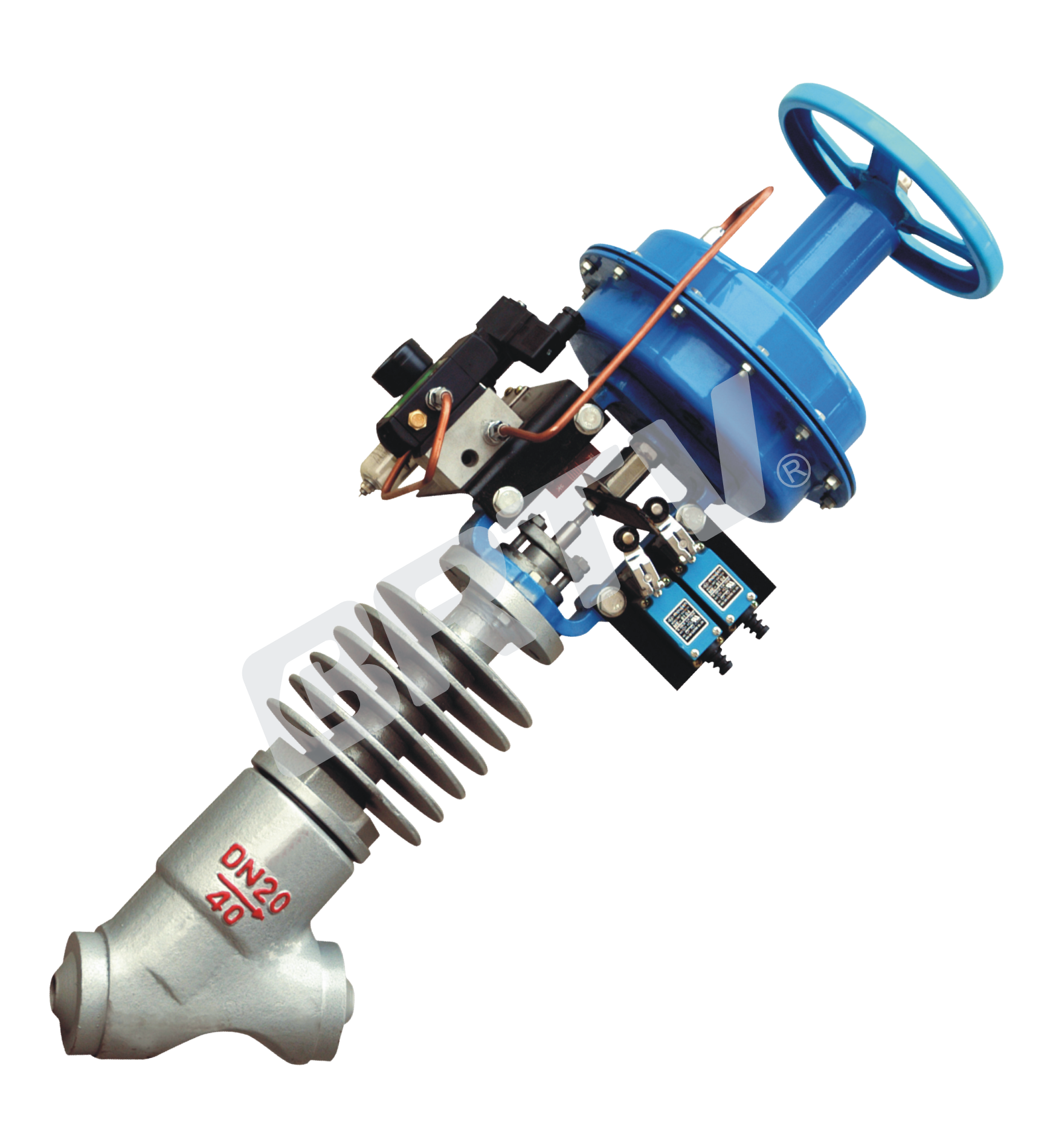
Product Advantages
The structure and optimal flow channel shape design of the inclined stem of the Y-type High-pressure Steam Trap. The valve has a high KV value by allowing the medium to pass through the entire flow channel in a nearly straight line manner (i.e. very small flow resistance). Different components designed with a modular concept can be freely combined and interchanged, and equipped with different accessories such as solenoid valves, holding valves, and row valves. Process switches and other components ensure the reliable use of drain valves in various complex situations. The whole machine has the following advantages:
Compact structure:Low flow resistance
Large circulation capacity:Stable and reliable
Zero Leakage:Movements maintainable
Applicable industry
Pneumatic and electric actuators can be used according to operating conditions, and are widely used in various industries such as petroleum and chemical for connecting or cutting off media in emission scenarios.
Product Features
- The Y–shaped approximate straight channel has the characteristics of high flow capacity and low flow resistance, making it particularly suitable for “discharge”;
- The sealing surface is welded with hard alloy and subjected to overall hardening treatment to improve sealing performance;
- The integral forging valve body has better pressure resistance and a more beautiful appearance;
- The upper mounted valve cover and packing box structure facilitate quick disassembly and on–site maintenance;
- The dual directional structure operates more stably and reliably;
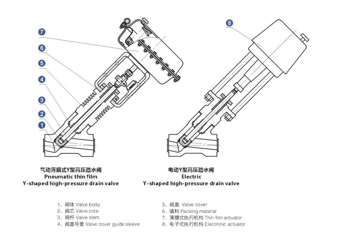
Valve body part
| Structural Categories | Y-shaped drain valve |
|---|
| Traffic Characteristics | Quick open |
| Valve Diameter | DN15–100 (1/2"–4") |
| Spool Type | Self-guided quick opening |
| Leakage Standard | VI level, zero leakage |
| Connection Method | Welding type, flange type |
| Nominal Pressure | ANSI 150, 300, 600, 900, 1500 (2.0, 5.0, 11.0, 15.0, 26.0 MPa) |
| Temperature | -29 ~ +250°C, -29 ~ +425°C, -29 ~ +593°C |
| Structure Type | Standard type, heat dissipation type |
Common materials for main components
| Valve Body and Valve Cover | 25, 25Cr2Mo1V, 0Cr18Ni9, A105, F11, F22, F304L, F316L |
|---|
| Valve Core and Seat | 304, F316, 1Cr17Ni2, 17-4PH, hard alloy surfacing ≥660 |
| Valve Stem | 304, 316, 1Cr17Ni2, 17-4PH |
| Filler | Flexible graphite woven with 316 wire |
| Spacer | 316 high-mesh flexible graphite pad |
| Membrane Cover | A3 |
| Corrugated Diaphragm | Reinforced nylon fabric nitrile rubber |
| Spring | 60Si2Mn |
Valve Structure And Composition
Pneumatic Action Mode
Double action
When the gas source fails, the valve is in the lost air position without a reset spring or thrust. Large is the preferred choice for cylinder type.
Air sealed (FO)
When the gas source fails, the actuator spring opens the valve.
Single action
When the gas source fails, the actuator spring will reset the valve to its original limit position (fully open or fully closed), there are gas open and gas closed types.
Gas Open (FC)
When the gas source fails, the actuator spring closes the valve.
Electric Action Mode
Air sealed (FO)
The power valve is closed (switch type).
Electric Open Circuit (FC)
Open the power valve (switch type).
Specifications And Technical Parameters
| Item | 20 | 15 | 25 | 32 | 40 | 50 | 65 | 80 | 100 |
|---|
| Rated Flow Coefficient Kv | 2.8 | 5 | 7 | 11 | 20 | 30 | 48 | 75 | 120 |
| Rated Stroke L (mm) | 25 | 25 | 25 | 30 | 30 | 30 | 50 | 50 | 100 |
| Pneumatic Thin Film Actuator Model | PM400 | PM400 | PM400 | PM600 | PM600 | PM600 | PM1000 | PM1000 | – |
| Pneumatic Piston Actuator Model | PS150 | PS150 | PS150 | PS200 | PS200 | PS200 | PS250 | PS250 | PS250 |
| Electronic Actuator Model | 361LSA20 / PSL202-204 | 361LSA20 / PSL202-204 | 361LSA20 / PSL202-204 | 361LSB50/65 / PSL204-210 | 361LSB50/65 / PSL204-210 | 361LSB50/65 / PSL204-210 | 361LSC65/99 / PSL210-314 | 361LSC65/99 / PSL210-314 | 361LSC65/99 / PSL210-314 |
| Nominal Pressure (MPa) | colspan=9 2.0, 5.0, 11.0, 15.0, 26.0 (150, 300, 600, 900, 1500 lb) | | | | | | | | |
| Inherent Flow Characteristics | colspan=9 Quick open | | | | | | | | |
| Leakage Level | colspan=9 VI level, zero leakage | | | | | | | | |
| Inherent Adjustable Ratio R | colspan=9 30 | | | | | | | | |
| Working Temperature (°C) | colspan=9 -29 ~ +593 | | | | | | | | |
| Gas Signal Range (kPa) | colspan=9 20100, 40200, 80~240 | | | | | | | | |
| Gas Source Pressure (MPa) | colspan=9 0.14~0.40 | | | | | | | | |
| Power Supply | colspan=9 220V AC, 380V AC | | | | | | | | |
Note:
(1) The data in the table is the standard configuration of our company and can be optionally selected according to user requirements.
(2) The performance indicators of this product comply with GB/T4213, JB/T7387, ANSI16.34.
Special Requirements
- Special inspection;
- Used under vacuum conditions;
- Complete oil and water removal treatment;
- Special media (such as oxygen);
- Copper prohibition treatment;
- Use stainless steel connectors;
- Special interfaces and piping;
- Specify the coating color;
Connection Size And Standard
Connection method: welding, flange (to be specified by the user)
Welding standards (groove size): butt welding according to ANSI B16.25, socket welding according to ANSI B16.11 or user specified
Execution mechanism gas signal interface: internal thread M10×1 M16×1.5, Rc1/4
Connection method: The valve body flange and end face distance can be manufactured according to user specified standards (such as GB, HG, JB, DIN, JIS, etc.)
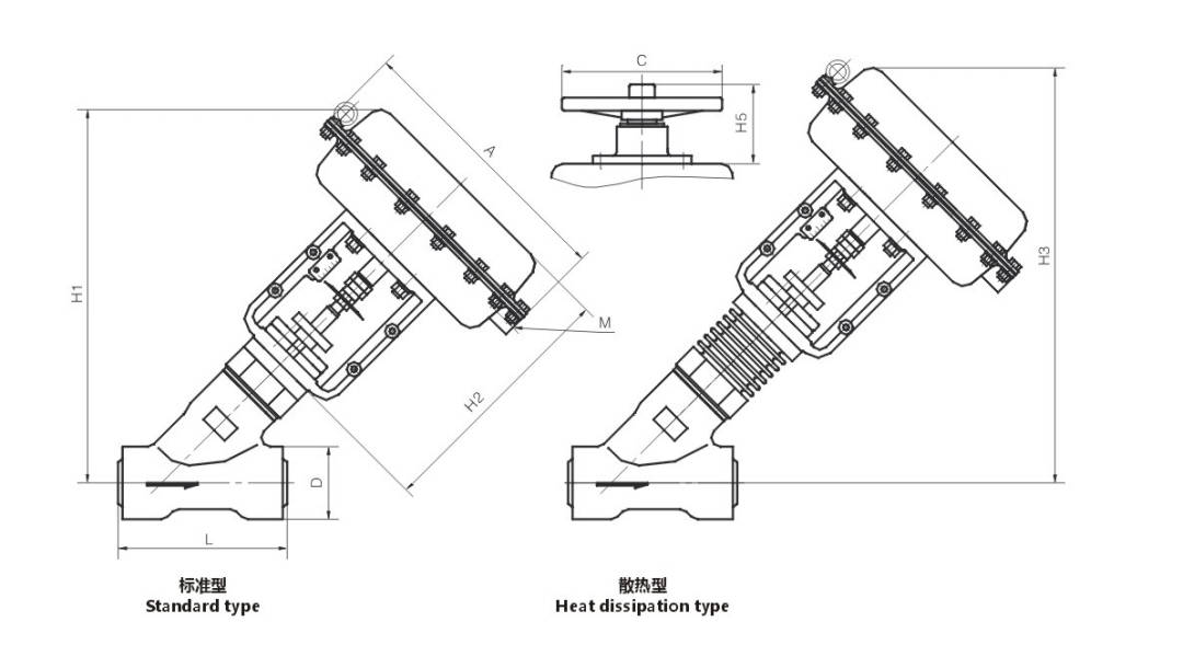
Dimensions And Weight / pneumatic Film
| Item | 15 | 20 | 25 | 32 | 40 | 50 | 65 | 80 | 100 |
|---|
| L | 152 | 162 | 162 | 180 | 180 | 270 | 325 | 325 | 380 |
| A | Φ308 | Φ308 | Φ308 | Φ394 | Φ394 | Φ504 | Φ504 | Φ375 | Φ375 |
| D | Φ58 | Φ58 | Φ58 | Φ81 | Φ81 | Φ92 | Φ108 | Φ108 | Φ122 |
| H1 | 442 | 442 | 442 | 480 | 480 | 510 | 550 | 550 | 670 |
| H2 | 260 | 260 | 260 | 282 | 282 | 282 | 362 | 362 | 362 |
| H3 | 505 | 505 | 505 | 555 | 555 | 590 | 650 | 650 | 680 |
| C | Φ220 | Φ220 | Φ220 | Φ220 | Φ220 | Φ220 | Φ270 | Φ270 | Φ270 |
| H5 | 182 | 182 | 182 | 182 | 182 | 182 | 240 | 240 | 240 |
| M | M10×1 | M10×1 | M10×1 | M10×1 | M10×1 | M10×1 | M16×1.5 | M16×1.5 | M16×1.5 |
| Weight (kg) | 15 | 15 | 15 | 25 | 25 | 32 | 45 | 50 | 60 |
Note: The weight in the table is for standard models without accessories such as handwheels.
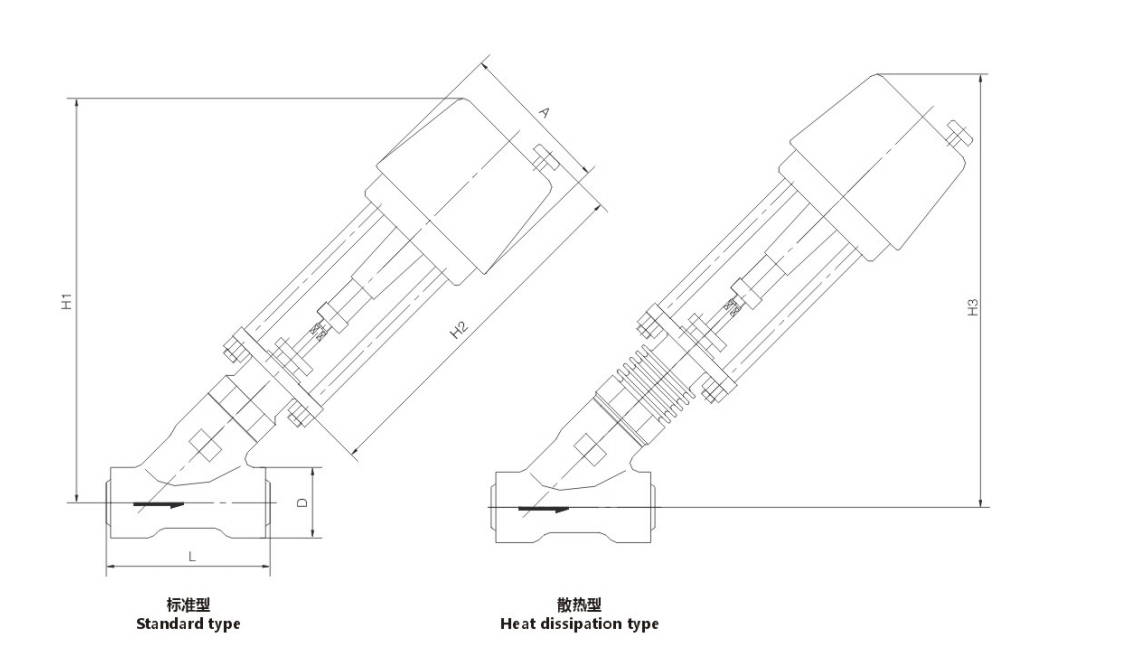
Dimensions And Weight / Electric
| Item | 15 | 20 | 25 | 32 | 40 | 50 | 65 | 80 | 100 |
|---|
| L | 152 | 162 | 162 | 180 | 180 | 270 | 325 | 325 | 380 |
| A | Φ180 | Φ180 | Φ180 | Φ190 | Φ190 | Φ190 | Φ190/220 | Φ190/220 | Φ190/220 |
| H1 | 560 | 560 | 560 | 620 | 620 | 650 | 700 | 700 | 725 |
| H2 | 490 | 490 | 490 | 520 | 520 | 520 | 520/825 | 520/825 | 520/825 |
| H3 | 630 | 630 | 630 | 695 | 695 | 730 | 810 | 810 | 835 |
| Weight (kg) | 20 | 20 | 20 | 28 | 28 | 40 | 65 | 75 | 95 |
Manufacturing Process
Step 1: Order and Design
Confirm the product specifications for the Y-type high-pressure steam trap based on the customer’s requirements for pressure rating, connection type, material, and operating conditions. The technical department completes the drawing design, structural verification, and manufacturing process review to ensure that subsequent production meets the requirements for high-pressure steam applications.
Step 2: Forging & Casting
Critical pressure-bearing components such as the valve body and valve cover are typically manufactured from forged or precision-cast blanks. For Y-type high-pressure steam traps, particular emphasis is placed on ensuring material strength, density, and pressure resistance, along with conducting visual inspections and verifying basic dimensions of the blanks.
Step 3: Machining
Precision machining is performed on components such as the valve body, valve seat, valve cover, and connection ends, including turning, drilling, tapping, and sealing surface finishing. The machining focus for the Y-type high-pressure steam trap is on ensuring the precision of internal flow passages, the surface finish of sealing surfaces, and the accuracy of all mating dimensions, thereby guaranteeing sealing performance and service life.
Step 4: Assembly
The valve plug, seat, lever mechanism, strainer components, and fasteners are assembled according to process requirements. During assembly, the sensitivity of the internal operating mechanism and the installation positions of all components must be strictly controlled to ensure stable opening and closing and smooth drainage.
Step 5: Testing & Quality Assurance
After assembly, the Y-type high-pressure steam trap undergoes shell strength testing, seal testing, operational performance testing, and visual inspection. Quality control personnel also verify dimensions, materials, and assembly quality to ensure the product meets factory standards and customer requirements.
Step 6: Painting and Finishing
After passing inspection, the product undergoes surface cleaning, rust prevention treatment, spray painting, and labeling. Finally, the finished product is packaged and stored to ensure the valve remains undamaged during transportation and is easily identifiable and installable by the customer.
Applications
Mainly applied in scenarios such as steam drainage of steam turbine unit extraction pipelines and boiler steam systems, it supports connection methods of socket-welding and butt-welding.
These valves are widely used in:
Agriculture and Irrigation
Factory Environment
Why Choose Us
Superior Quality

Our valves are manufactured using premium materials and undergo rigorous quality testing to ensure reliable performance in demanding industrial applications.
Advanced Technology

Equipped with state-of-the-art CNC machining centers and precision manufacturing equipment, we deliver valves with exceptional accuracy and consistency.
Competitive Pricing

Through optimized manufacturing processes and bulk material procurement, we offer high-quality valves at competitive prices without compromising on quality.
Expert Support

Our experienced technical team provides comprehensive support from product selection to after-sales service, ensuring optimal valve performance for your specific application.