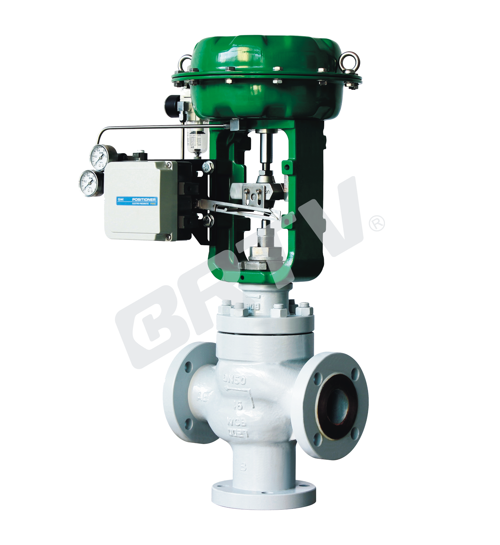
Three Way Diverting Control Valve
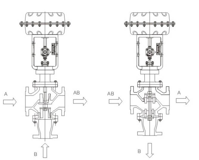
Three Way Diverting Control Valve is used in the occasion of adjusting three pipe tee. It has two types: HMT and HDT. When the nominal diameter and pressure difference is small, the junction valve can be used for diversion occasion. When nominal diameter is more than 80mm or pressure difference is larger, it only use for branch occasion.
It is equipped with multi–spring pneumatic diaphragm actuator or electric actuator. It has characteristics of small size, light weight, large output force, easy installation.
Standard Specifications
| Manner | Straight Through Single Seat Cast Ball Valve |
|---|
| Nominal Diameter | 25, 40, 50, 65, 80, 100, 125, 150 mm |
| Nominal Pressure | ANSI Class 150, 300, 600; JIS 10K, 20K, 30K, 40K; PN 1.6, 4.0, 6.4 MPa |
| Type of Connection | Flange Type: FF, RF, RJ, TG, MFM |
| Body and Bonnet Material | SCHP2/WCB, SCHP21/WC6, SCS13A/CF8, SCS14A/CF8M, SCS16A/CF3M, Ti – Operating temperature and pressure range of various materials |
| Bonnet Manner | Normal Temperature Type: −17 ~ +230°C; Elongation Type I: −45 ~ −17°C and +230 ~ +566°C |
| Gland Manner | Screw Fastening Type |
| Packing | V-Type PTFE Packing, Graphite Packing |
| Surface Coating / Gasket | Plain Type, Zigzag Type / Stainless Steel (SUS304, SUS316, SUS316L) and other alloys. Blue (Epoxy). When the valve body material is stainless steel, coating is not applied. |
Cv Value and Stroke
| Item | DN25 | DN32 | DN40 | DN50 | DN65 | DN80 | DN100 | DN125 | DN150 |
|---|
| Seat Diameter | 20 | 25 | 32 | 40 | 65 | 80 | 100 | 125 | 150 |
| Rated Cv | 6.3 | 10 | 23 | 40 | 63 | 100 | 160 | 250 | 400 |
| Rated Stroke (mm) | 16 | 16 | 25 | 25 | 40 | 40 | 40 | 60 | 60 |
Actuator
| Item | Pneumatic Diaphragm Type | Cylinder Piston Type (Single Action) | Cylinder Piston Type (Double Action) | Electronic Type | Intelligent Type |
|---|
| Model | ZJHA/B | ZTCLS | ZTCL | 381 Series | ZM Series |
| Type | Multiple Springs Type | Single Action | Double Action | 381 Series | ZM Series |
| Service | Regulation | Regulation | Regulation | Regulation | Regulation |
| Supply Gas Pressure / Supply Voltage | Supply Gas Pressure (spring range): 140–100 kPa; 160–200 kPa; 280–400 kPa; 400–840 kPa | Supply Gas Pressure: 400–700 kPa | Supply Gas Pressure: 400–700 kPa | Voltage: 220/380V 50Hz; Input Signal: 4–20 mA DC | Voltage: 220/380V 50Hz; Input Signal: 4–20 mA DC |
| Connector | Air Piping: RC1/4 | Air Piping: G1/8, G1/4, G1/2, G3/8 | Air Piping: G1/8, G1/4, G1/2, G3/8 | Wiring: 2-PF3/4 | Wiring: PG13.5 |
| Positive Action | Adding Pressure, Valve Will Be Closed | Adding Pressure, Valve Will Be Closed | Adding Pressure, Valve Will Be Closed | Inputting the Signal, Valve Will Be Closed | Inputting the Signal, Valve Will Be Closed |
| Negative Action | Adding Pressure, Valve Will Be Opened | Adding Pressure, Valve Will Be Opened | Adding Pressure, Valve Will Be Opened | Inputting the Signal, Valve Will Be Opened | Inputting the Signal, Valve Will Be Opened |
| Hysteresis | ≤1% FS (with Positioner); ≤3% FS (without Positioner) | ≤1% FS (with Positioner); ≤3% FS (without Positioner) | ≤1% FS (with Positioner); ≤3% FS (without Positioner) | ≤1% FS | ≤1% FS |
| Limit of Intrinsic Error | ≤±1% FS (with Positioner); ≤±5% FS (without Positioner); ≤±2% FS (HA1 type); ≤±1% FS (with Positioner); ≤±5% FS (no Positioner); ≤±2% FS (Match type HA1) | ≤±1% FS (with Positioner); ≤±5% FS (without Positioner) | ≤±1% FS (with Positioner); ≤±5% FS (without Positioner) | ≤±1% FS | ≤±1% FS |
| Ambient Temperature | Normal Temperature Type: −30 ~ +70°C; High Temperature Type: 0 ~ +100°C; Low Temperature Type: −40 ~ +40°C | Normal Temperature Type: −20 ~ +60°C; High Temperature Type: 0 ~ +100°C; Low Temperature Type: −50 ~ +60°C | Normal Temperature Type: −20 ~ +60°C; High Temperature Type: 0 ~ +100°C; Low Temperature Type: −50 ~ +60°C | −20 ~ +70°C | −25 ~ +70°C |
| Painting Color | Blue Scale 10B5/10 | Blue Scale 10B5/10 | Blue Scale 10B5/10 | — | — |
| Accessory | Positioner / Air Filtration Pressure Reducing Valve / Transmitter / Handwheel | Positioner / Air Filtration Pressure Reducing Valve / Transmitter / Handwheel | Positioner / Air Filtration Pressure Reducing Valve / Transmitter / Handwheel | Integrated Type | Integrated Type |
Model Selection Parameter Table
| Seat Diameter (mm) | 25 | 32 | 40 | 50 | 65 | 80 | 100 | 125 | 150 |
|---|
| Rated Flow Cv Value | 8.5 | 13 | 21 | 34 | 53 | 85 | 135 | 210 | 340 |
| Nominal Diameter | Stroke | 25 | 32 | 40 | 50 | 65 | 80 | 100 | 125 | 150 |
|---|
| DN25 | 16 mm | ★ | | | | | | | | |
| DN32 | 25 mm | | ★ | | | | | | | |
| DN40 | 25 mm | | ● | ★ | | | | | | |
| DN50 | 25 mm | | ● | ● | ★ | | | | | |
| DN65 | 40 mm | | | | | ★ | | | | |
| DN80 | 40 mm | | | | | ● | ★ | | | |
| DN100 | 40 mm | | | | | ● | ● | ★ | | |
| DN125 | 60 mm | | | | | | | | ★ | |
| DN150 | 60 mm | | | | | | | | ● | ★ |
| DN200 | 60 mm | | | | | | | | ● | ● |
| DN250 | 100 mm | | | | | | | | | ● |
| DN300 | 100 mm | | | | | | | | | |
★ standard type, ● recommended type
Pneumatic Actuator Diaphragm Active Area
| Actuator Model | Active Area Ae (cm²) |
|---|
| ZHA/B-22 | 350 |
| ZHA/B-23 | 350 |
| ZHA/B-34 | 560 |
| ZHA/B-45 | 900 |
Allowable Pressure Differential of Metal Seal (MPa)
| Action | Spring Range | 25 | 32 | 40 | 50 | 65 | 80 | 100 | 125 | 150 |
|---|
| Open | 20–100 kPa | 0.7 | 0.44 | 0.28 | 0.18 | 0.17 | 0.11 | 0.07 | 0.07 | 0.05 |
| Open | 40–200 kPa | 2.14 | 1.31 | 0.84 | 0.53 | 0.51 | 0.33 | 0.21 | 0.22 | 0.15 |
| Open | 80–240 kPa | 4.99 | 3.05 | 1.95 | 1.25 | 1.18 | 0.78 | 0.50 | 0.51 | 0.36 |
| Close | 20–100 kPa | 2.14 | 0.87 | 0.56 | 0.35 | 0.34 | 0.22 | 0.14 | 0.15 | 0.10 |
| Close | 40–200 kPa | 6.4 | 5.86 | 3.64 | 2.30 | 2.21 | 1.43 | 0.91 | 0.95 | 0.66 |
| Close | 80–240 kPa | 6.4 | 6.4 | 5.04 | 3.18 | 3.06 | 1.98 | 1.26 | 1.32 | 0.92 |
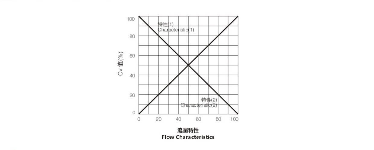
Typical Flow Characteristic of Valve
The Value of Allowable Pressure Difference
Pneumatic Three Way Mixing Control Valve
Unit:mm
| Actuator Specification | Supply Gas Pressure (MPa) | Spring Range (MPa) | Positioner | 20 | 25 | 40 | 50 | 65 | 80 | 100 | 125 | 150 |
|---|
| ZJHA/B-23 | 0.14 | 0.02–0.10 | | 0.79 | 0.49 | 0.33 | 0.20 | 0.12 | 0.09 | 0.05 | – | – |
| ZJHA/B-23 | 0.14 | 0.02–0.10 | | 0.04 | 3.5 | 2.3 | 1.4 | 0.86 | 0.62 | 0.34 | – | – |
| ZJHA/B-23 | 0.35 | 0.08–0.24 | | 1.6 | 0.99 | (0.67) | 0.39 | (0.24) | (0.18) | (0.10) | – | – |
| ZJHA/B-34 | 0.14 | 0.02–0.10 | Have | – | – | 0.59 | 0.35 | 0.22 | 0.16 | 0.09 | 0.05 | 0.04 |
| ZJHA/B-34 | 0.35 | 0.08–0.24 | Have | – | – | 4.0 | 2.5 | 1.53 | 1.1 | 0.02 | 0.30 | 0.27 |
| ZJHA/B-34 | 0.35 | 0.08–0.24 | Have | – | – | (1.2) | 0.71 | (0.43) | (0.31) | (0.18) | (0.10) | (0.08) |
| ZJHA/B-45 | 0.14 | 0.02–0.10 | | – | – | – | – | 0.37 | 0.26 | 0.15 | 0.10 | 0.06 |
| ZJHA/B-45 | 0.35 | 0.08–0.24 | | – | – | – | – | 2.7 | 1.9 | 1.07 | 0.69 | 0.47 |
| ZJHA/B-45 | 0.35 | 0.08–0.24 | | – | – | – | – | (0.76) | (0.54) | (0.30) | (0.20) | (0.13) |
Pneumatic Three Way Diverting Control Valve
Unit:MPa
| Actuator | Supply Gas Pressure (MPa) | Spring Range (MPa) | Positioner | 80 | 100 | 125 | 150 |
|---|
| ZJHA/B-23 | 0.14 | 0.02–0.10 | | 0.09 | 0.05 | – | – |
| ZJHA/B-23 | 0.35 | 0.08–0.24 | | 0.62 | 0.34 | – | – |
| ZJHA/B-34 | 0.14 | 0.02–0.10 | Have | 0.16 | 0.09 | 0.05 | 0.04 |
| ZJHA/B-34 | 0.35 | 0.08–0.24 | Have | 1.1 | 0.62 | 0.39 | 0.27 |
| ZJHA/B-45 | 0.14 | 0.02–0.10 | | 0.26 | 0.15 | 0.10 | 0.06 |
| ZJHA/B-45 | 0.35 | 0.08–0.24 | | 1.9 | 1.07 | 0.69 | 0.47 |
Note: the number ① above is the shunt occasion pressure difference, the rest is same on interflow and shunt.
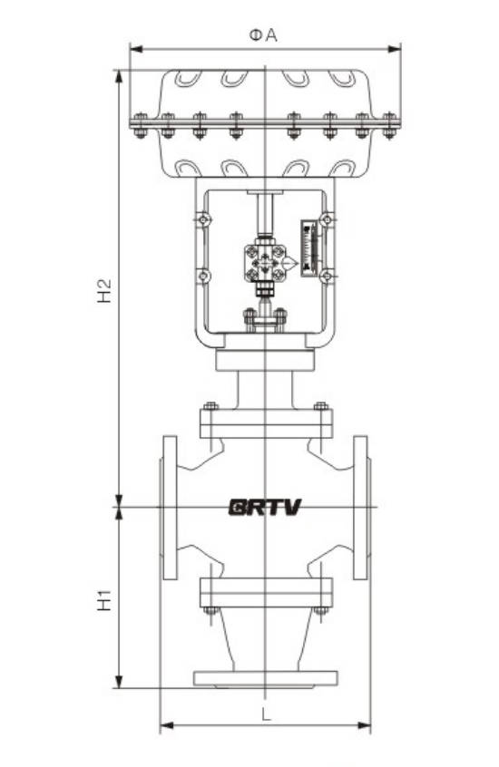
Unit:MPa
| NPS | DN | HMT L | HMT H1 | HMT H2 | HDT L | HDT H1 | HDT H2 | ΦA |
|---|
| 1" | 25 | 184 | 145 | 475 | 184 | 145 | 475 | 285 |
| 1 1/2" | 40 | 222 | 205 | 495 | 222 | 205 | 495 | 285 |
| 2" | 50 | 254 | 230 | 510 | 254 | 230 | 510 | 285 |
| 2 1/2" | 65 | 276 | 260 | 670 | 276 | 260 | 670 | 365 |
| 3" | 80 | 298 | 280 | 705 | 370 | 300 | 705 | 365 |
| 4" | 100 | 352 | 330 | 745 | 400 | 330 | 745 | 365 |
| 5" | 125 | 403 | 370 | 764 | 460 | 370 | 764 | 480 |
| 6" | 150 | 451 | 410 | 791 | 530 | 450 | 791 | 480 |
Manufacturing Process
Step 1: Order and Design
Confirm customer requirements, including size, pressure rating, material, flow coefficient, connection type, and actuator configuration.
For the three way diverting control valve, engineers prepare drawings, select body structure, trim design, and sealing type to ensure accurate flow diversion performance.
Step 2: Forging & Casting
The main pressure-bearing parts such as valve body, bonnet, and flanges are produced by casting or forging according to the material specification.
For a three way diverting control valve, special attention is paid to the internal flow passages of the three-way body to ensure sound structure and stable flow distribution.
Step 3: Machining
After raw casting inspection, CNC machining is carried out for the valve body, seat pocket, stem hole, flange face, and internal trim parts.
The machining of the three way diverting control valve requires high precision on the three-port dimensions and sealing surfaces to guarantee reliable diverting control.
Step 4: Assembly
All qualified parts are cleaned and assembled, including valve plug, seat, stem, bonnet, actuator, positioner, and accessories.
During three way diverting control valve assembly, technicians carefully adjust stem travel and plug position to achieve smooth switching and accurate flow regulation.
Step 5: Testing & Quality Assurance
Each valve undergoes pressure test, leakage test, stroke calibration, and functional inspection.
For the three way diverting control valve, flow direction performance, shut-off capability, and actuator response are checked to ensure the valve meets application and quality standards.
Step 6: Painting and Finishing
After testing approval, the valve surface is cleaned, painted, labeled, and packed. Final finishing includes nameplate confirmation, protection of flange faces, and export-safe packaging before shipment.
Applications
Mainly used in water treatment plants, power plants, steel mills, paper mills, chemical plants, catering and other systems for water supply and drainage systems.
These valves are widely used in:
Agriculture and Irrigation
Factory Environment
Why Choose Us
Superior Quality

Our valves are manufactured using premium materials and undergo rigorous quality testing to ensure reliable performance in demanding industrial applications.
Advanced Technology

Equipped with state-of-the-art CNC machining centers and precision manufacturing equipment, we deliver valves with exceptional accuracy and consistency.
Competitive Pricing

Through optimized manufacturing processes and bulk material procurement, we offer high-quality valves at competitive prices without compromising on quality.
Expert Support

Our experienced technical team provides comprehensive support from product selection to after-sales service, ensuring optimal valve performance for your specific application.