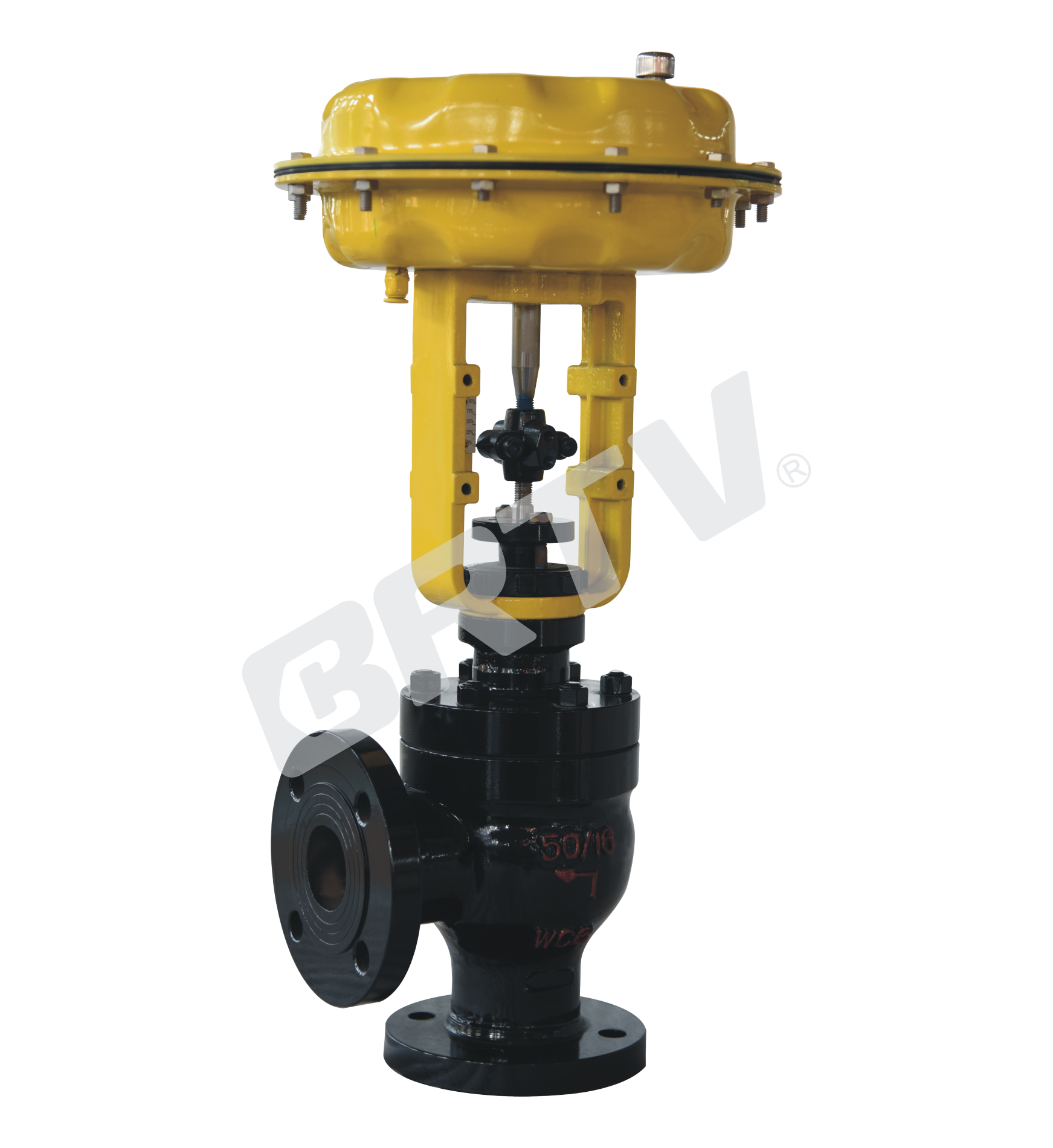
Single Seat Angle Type Control Valve
Single Seat Angle Type Control Valve is a top–guided single seat control valve. It has advantages of small pressure rise loss, large flow, and wide adjustable range. Besides, it has high accuracy of flow characteristic curve.
The valve core adopts pressure balance structure. The control valve is equipped with multi–spring diaphragm actuator or electric actuator, and has compact structure, large output torque.
Standard Specifications
| Item | Specification |
|---|
| Manner | Angle Type Single Seat Casting Ball Valve |
| Nominal Diameter | 15, 20, 25, 40, 50, 65, 80, 100, 125, 150, 200 mm |
| Nominal Pressure | ANSI Class 125, 150, 300, 600; JIS 10K, 20K, 30K, 40K; PN 1.6, 4.0, 6.4 MPa |
| Type of Connection | Flange Type: FF, RF, RJ, TG, MFM; Weld Type: SW (40–50 mm), BW (65–200 mm) |
| Material of Body and Bonnet | SCPH2/WCB, SCPH21/WC6, SCS13A/CF8, SCS14A/CF8M, SCS16A/CF3M; titanium and other alloys |
| Bonnet Manner | Normal Temperature Type: −17 ~ +230 °C; Elongation Type I: −45 ~ −17 °C and +230 ~ +566 °C; Elongation Type II: −100 ~ −45 °C |
| Gland Manner | Screw Fastening Type |
| Packing | V-Type PTFE Packing; Graphite Packing |
| Gasket | Plain Type; Zigzag Type; Stainless Steel (SUS304, SUS316, SUS316L) and other alloys |
| Surface Coating | Blue (Epoxy). When the valve body material is stainless steel, coating is not applied |
Cv Value and Stroke
| Nominal Diameter (mm) | 15 | 15 | 15 | 20 | 20 | 25 | 25 | 32 | 32 | 40 | 40 | 40 | 50 | 50 | 50 |
|---|
| Seat Diameter (mm) | 10 | 12 | 15 | 15 | 20 | 20 | 25 | 25 | 32 | 25 | 32 | 40 | 32 | 40 | 50 |
| Rated Cv | 1.6 | 2.5 | 4 | 4 | 6.3 | 6.3 | 10 | 10 | 17 | 10 | 17 | 24 | 17 | 24 | 40 |
| Rated Stroke (mm) | 25 | 25 | 25 | 25 | 25 | 25 | 25 | 25 | 25 | 25 | 25 | 25 | 25 | 25 | 25 |
| Nominal Diameter (mm) | 65 | 65 | 65 | 80 | 80 | 80 | 100 | 100 | 100 | 125 | 125 | 125 | 150 | 150 | 150 | 200 | 200 | 200 |
|---|
| Seat Diameter (mm) | 40 | 50 | 65 | 50 | 65 | 80 | 65 | 80 | 100 | 80 | 100 | 125 | 100 | 125 | 150 | 125 | 150 | 200 |
| Rated Cv | 24 | 40 | 63 | 40 | 63 | 100 | 63 | 100 | 160 | 100 | 160 | 250 | 160 | 250 | 400 | 250 | 400 | 630 |
| Rated Stroke (mm) | 40 | 40 | 40 | 40 | 40 | 40 | 40 | 40 | 40 | 60 | 60 | 60 | 60 | 60 | 60 | 60 | 60 | 60 |
Actuator
| Item | Pneumatic Diaphragm Type | Cylinder Piston Type (Single Action) | Cylinder Piston Type (Double Action) | Electronic Type | Intelligent Type |
|---|
| Model | ZJHA/B | ZTCLS | ZTCL | 381 Series | ZM Series |
| Type | Multiple Springs Type | Single Action | Double Action | | |
| Service | Regulation | Regulation | Regulation | Regulation | Regulation |
| Supply Gas Pressure / Supply Voltage | Supply Gas Pressure (spring range): 140 (20–100) kPa; 160 (20–100) kPa; 280 (80–240) kPa; 400 (80–240) kPa | Supply Gas Pressure: 400–700 kPa | Supply Gas Pressure: 400–700 kPa | Voltage: 220 / 380 V 50 Hz; Input Signal: 4–20 mA DC | Voltage: 220 / 380 V 50 Hz; Input Signal: 4–20 mA DC |
| Connector | Air Piping: RC1/4 | Air Piping: G1/8, G1/4, G1/2, G3/8 | Air Piping: G1/8, G1/4, G1/2, G3/8 | Wiring: 2-PF3/4 | Wiring: PG13.5 |
| Positive Action | Adding Pressure — Valve Will Be Closed | Adding Pressure — Valve Will Be Closed | Adding Pressure — Valve Will Be Closed | Inputting the Signal — Valve Will Be Closed | Inputting the Signal — Valve Will Be Closed |
| Negative Action | Adding Pressure — Valve Will Be Opened | Adding Pressure — Valve Will Be Opened | Adding Pressure — Valve Will Be Opened | Inputting the Signal — Valve Will Be Opened | Inputting the Signal — Valve Will Be Opened |
| Hysteresis | ≤1% FS (with Positioner); ≤3% FS (no Positioner) | ≤1% FS (with Positioner); ≤3% FS (no Positioner) | ≤1% FS (with Positioner); ≤3% FS (no Positioner) | ≤1% FS | ≤1% FS |
| Limit of Intrinsic Error | ≤1% FS (with Positioner); ≤3% FS (no Positioner) | ≤1% FS (with Positioner); ≤3% FS (no Positioner) | ≤1% FS (with Positioner); ≤3% FS (no Positioner) | ≤1% FS | ≤1% FS |
| Ambient Temperature | Normal Temperature: −30 ~ +70 °C; High Temperature: 0 ~ +100 °C; Low Temperature: −40 ~ +40 °C | Normal Temperature: −20 ~ +60 °C; High Temperature: 0 ~ +100 °C; Low Temperature: −50 ~ +60 °C | Normal Temperature: −20 ~ +60 °C; High Temperature: 0 ~ +100 °C; Low Temperature: −50 ~ +60 °C | −20 ~ +70 °C | −25 ~ +70 °C |
| Painting Color | Blue Scale 1085/10 | Blue Scale 1085/10 | Blue Scale 1085/10 | | |
| Accessory | Positioner; Air Filtration Pressure Reducing Valve; Transmitter; Handwheel | Positioner; Air Filtration Pressure Reducing Valve; Transmitter; Handwheel | Positioner; Air Filtration Pressure Reducing Valve; Transmitter; Handwheel | Integrated Type | Integrated Type |
Model Selection Parameter Table
Optional coefficient of flow Cv (★ standard type: ● recommend type: ○ customized type)
| Section | Item | 10 | 12 | 15 | 20 | 25 | 32 | 40 | 50 | 65 | 80 | 100 | 125 | 150 | 200 |
|---|
| Rated Flow Cv Value | Equal Percentage Cv | 1.6 | 2.5 | 4 | 6.3 | 10 | 16 | 25 | 40 | 63 | 100 | 160 | 250 | 400 | 630 |
| Rated Flow Cv Value | Straight Cv | 1.8 | 2.8 | 4.4 | 6.9 | 11 | 17.6 | 27.5 | 44 | 69 | 110 | 176 | 275 | 440 | 690 |
| Nominal Diameter | DN20 (16 mm stroke) | ● | ● | ● | ★ | | | | | | | | | | |
| Nominal Diameter | DN25 (16 mm stroke) | ● | ● | ● | ● | ★ | | | | | | | | | |
| Nominal Diameter | DN32 (25 mm stroke) | ○ | ○ | ○ | ○ | ○ | ★ | | | | | | | | |
| Nominal Diameter | DN40 (25 mm stroke) | | ○ | ○ | ○ | ○ | ● | ★ | | | | | | | |
| Nominal Diameter | DN50 (25 mm stroke) | | | ○ | ○ | ○ | ● | ● | ★ | | | | | | |
| Nominal Diameter | DN65 (40 mm stroke) | | | | | | ○ | ○ | ○ | ★ | | | | | |
| Nominal Diameter | DN80 (40 mm stroke) | | | | | | ○ | ○ | ○ | ● | ★ | | | | |
| Nominal Diameter | DN100 (40 mm stroke) | | | | | | ○ | ○ | ○ | ● | ● | ★ | | | |
| Nominal Diameter | DN125 (40 mm stroke) | | | | | | | | ○ | ○ | ○ | ★ | | | |
| Nominal Diameter | DN150 (60 mm stroke) | | | | | | | | | ○ | ○ | ● | ★ | | |
| Nominal Diameter | DN200 (60 mm stroke) | | | | | | | | | | ○ | ○ | ● | ● | ★ |
| Pneumatic Actuator Diaphragm Area | ZJHA/B-22 | 350 | | | | | | | | | | | | | |
| Pneumatic Actuator Diaphragm Area | ZJHA/B-23 | | 350 | | | | | | | | | | | | |
| Pneumatic Actuator Diaphragm Area | ZJHA/B-34 | | | 560 | | | | | | | | | | | |
| Pneumatic Actuator Diaphragm Area | ZJHA/B-45 | | | | 900 | | | | | | | | | | |
| Allowable Pressure Differential (Open) | 20–100 kPa | 4.46 | 3.09 | 1.98 | 1.16 | 0.7 | 0.44 | 0.28 | 0.18 | 0.17 | 0.11 | 0.07 | 0.07 | 0.05 | 0.03 |
| Allowable Pressure Differential (Open) | 40–200 kPa | 6.4 | 6.4 | 5.94 | 3.34 | 2.14 | 1.31 | 0.84 | 0.53 | 0.51 | 0.33 | 0.21 | 0.22 | 0.15 | 0.09 |
| Allowable Pressure Differential (Open) | 80–240 kPa | 6.4 | 6.4 | 6.4 | 6.4 | 4.99 | 3.05 | 1.95 | 1.25 | 1.18 | 0.78 | 0.5 | 0.51 | 0.36 | 0.21 |
| Allowable Pressure Differential (Close) | 20–100 kPa | 6.4 | 6.19 | 3.96 | 2.23 | 2.14 | 0.87 | 0.56 | 0.35 | 0.34 | 0.22 | 0.14 | 0.15 | 0.1 | 0.06 |
| Allowable Pressure Differential (Close) | 40–200 kPa | 6.4 | 6.4 | 6.4 | 6.4 | 6.4 | 5.86 | 3.64 | 2.3 | 2.21 | 1.43 | 0.91 | 0.95 | 0.66 | 0.37 |
| Allowable Pressure Differential (Close) | 80–240 kPa | 6.4 | 6.4 | 6.4 | 6.4 | 6.4 | 6.4 | 5.04 | 3.18 | 3.06 | 1.98 | 1.26 | 1.32 | 0.92 | 0.52 |
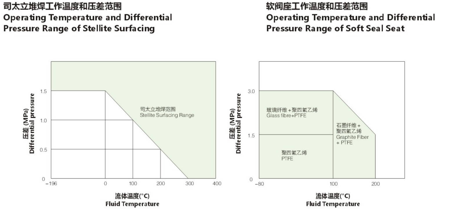
The Material of Valve and Components, Range of Using Temperature · Allowable Leakage of Seat
Body Material: Carbon Steel
| Item | Property | Option 1 | Option 2 | Option 3 |
|---|
| Body Material | | SCPH2/A216-WCB, SCPH21/A217-WC5, SCPL1/A352-LCB | | |
| Core | Material | SUS304/316 | SUS304/316 | SUS304/316 |
| Core | Treatment | – | R.TFE | SS/SF |
| Seat | Material | SUS304/316 | SUS304/316 | SUS304/316 |
| Seat | Treatment | – | – | SS/SF |
| Guide Sleeve | Material | SUS420 | SUS420 | SUS420 |
| Guide Sleeve | Treatment | HT | HT | HT |
| Gasket | Material | SUS316L | SUS316L | SUS316L |
| Allowable Leakage of Seat | ANSI | Class IV | Class VI | Class IV |
| Allowable Leakage of Seat | Rated CvX | 0.01% | Non-Leakage | 0.01% |
| Operating Temperature | SCPH2/WCB Body | −17 ~ +425 °C | −17 ~ +230 °C | −17 ~ +425 °C |
| Operating Temperature | SCPH21/WC6 Body | −17 ~ +566 °C | −17 ~ +230 °C | −17 ~ +566 °C |
| Operating Temperature | SCPL1/LCB Body | −45 ~ +350 °C | −45 ~ +230 °C | −45 ~ +350 °C |
R.TFE : Reinforced PTFE HT : Heat Treatment ST : Surfacing Staitalai Alloy SS : Partial Surfacing Staitalai Alloys SF : All Surfacing Staitalai Alloys
Body Material: Stainless Steel
| Item | Property | Option 1 | Option 2 | Option 3 |
|---|
| Body Material | | SCS13A/CF8, SCS14A/CF8M, SCS16A/CF3M | | |
| Core | Material | SUS304/316/316L | SUS304/316 | SUS304/316/316L |
| Core | Treatment | – | R.TFE | SS/SF |
| Seat | Material | SUS304/316/316L | SUS304/316/316L | SUS304/316/316L |
| Seat | Treatment | – | – | SS/SF |
| Guide Sleeve | Material | SUS304/316/316L | SUS304/316/316L | SUS304/316/316L |
| Guide Sleeve | Treatment | – | R.TFE | ST |
| Gasket | Material | SUS316L | SUS316L | SUS316L |
| Allowable Leakage of Seat | ANSI | Class IV | Class VI | Class IV |
| Allowable Leakage of Seat | Rated CvX | 0.01% | Non-Leakage | 0.01% |
| Operating Temperature | | −196 ~ +566 °C | −45 ~ +230 °C | −196 ~ +566 °C |
Allowable Differential Pressure
Multi-spring Diaphragm Actuator
Unit:MPa
| Actuator Model | Air Pressure (kPa) | Spring Range (kPa) | 3/4 (20) | 1 (25) | 1 1/4 (32) | 1 1/2 (40) | 2 (50) | 2 1/2 (65) | 3 (80) | 4 (100) | 5 (125) | 6 (150) | 8 (200) |
|---|
| ZJHA/B-22 | 140 | 20–100 | 1.17 | 0.75 | – | – | – | – | – | – | – | – | – |
| ZJHA/B-22 | 240 | 40–200 | 2.73 | 1.75 | – | – | – | – | – | – | – | – | – |
| ZJHA/B-22 | 300 | 80–240 | 5.85 | 3.75 | – | – | – | – | – | – | – | – | – |
| ZJHA/B-23 | 140 | 20–100 | 1.64 | 1.05 | 0.63 | 0.40 | 0.26 | – | – | – | – | – | – |
| ZJHA/B-23 | 240 | 40–200 | 3.82 | 2.45 | 1.49 | 0.96 | 0.61 | – | – | – | – | – | – |
| ZJHA/B-23 | 300 | 80–240 | 8.19 | 5.24 | 3.19 | 2.05 | 1.31 | – | – | – | – | – | – |
| ZJHA/B-34 | 140 | 20–100 | – | – | 1.02 | 0.66 | 0.42 | 0.24 | 0.16 | 0.10 | – | – | – |
| ZJHA/B-34 | 240 | 40–200 | – | – | 2.38 | 1.53 | 0.98 | 0.58 | 0.38 | 0.24 | – | – | – |
| ZJHA/B-34 | 300 | 80–240 | – | – | 5.12 | 3.28 | 2.10 | 1.24 | 0.82 | 0.52 | – | – | – |
| ZJHA/B-45 | 140 | 20–100 | – | – | – | – | – | 0.40 | 0.26 | 0.17 | 0.11 | 0.07 | 0.02 |
| ZJHA/B-45 | 240 | 40–200 | – | – | – | – | – | 0.93 | 0.61 | 0.39 | 0.25 | 0.17 | 0.07 |
| ZJHA/B-45 | 300 | 80–240 | – | – | – | – | – | 1.98 | 1.32 | 0.84 | 0.54 | 0.37 | 0.16 |
381L Series of Electronic Actuator
Unit:MPa
| Model | Voltage Rating | 3/4 (20) | 1 (25) | 1 1/4 (32) | 1 1/2 (40) | 2 (50) | 2 1/2 (65) | 3 (80) | 4 (100) | 5 (125) | 6 (150) | 8 (200) |
|---|
| 381LSA-08 | 110V / 220V / 380V | 2.38 | 1.52 | 0.93 | 0.59 | 0.38 | – | – | – | – | – | – |
| 381LSA-08 | 110V / 220V / 380V | 1.91 | 1.22 | 0.74 | 0.47 | 0.30 | – | – | – | – | – | – |
| 381LSA-20 | 110V / 220V / 380V | 4.77 | 3.05 | 1.86 | 1.19 | 0.76 | 0.45 | – | – | – | – | – |
| 381LSA-20 | 110V / 220V / 380V | 3.82 | 2.44 | 1.49 | 0.95 | 0.61 | 0.36 | – | – | – | – | – |
| 381LSB-30 | 110V / 220V / 380V | – | – | 2.79 | 1.79 | 1.14 | 0.67 | 1.21 | 0.28 | 0.18 | 0.12 | 0.03 |
| 381LSB-30 | 110V / 220V / 380V | – | – | 2.23 | 1.43 | 0.91 | 0.54 | 0.96 | 0.22 | 0.14 | 0.10 | 0.02 |
| 381LSB-50 | 110V / 220V / 380V | – | – | 4.66 | 2.98 | 1.91 | 1.13 | 1.51 | 0.47 | 0.30 | 0.21 | 0.08 |
| 381LSB-50 | 110V / 220V / 380V | – | – | 3.73 | 2.38 | 1.52 | 0.90 | 1.20 | 0.38 | 0.24 | 0.16 | 0.06 |
| 381LSC-65 | 110V / 220V / 380V | – | – | – | – | – | 1.35 | 2.34 | 0.57 | 0.36 | 0.25 | 0.11 |
| 381LSC-65 | 110V / 220V / 380V | – | – | – | – | – | 1.08 | 1.87 | 0.45 | 0.29 | 0.20 | 0.08 |
| 381LSC-99 | 110V / 220V / 380V | – | – | – | – | – | 2.26 | 2.92 | 0.95 | 0.61 | 0.42 | 0.20 |
| 381LSC-99 | 110V / 220V / 380V | – | – | – | – | – | 1.80 | 2.33 | 0.76 | 0.48 | 0.33 | 0.15 |
| 381LSC-160 | 110V / 220V / 380V | – | – | – | – | – | – | – | – | 0.97 | 0.67 | 0.35 |
| 381LSC-160 | 110V / 220V / 380V | – | – | – | – | – | – | – | – | 0.78 | 0.54 | 0.27 |
Outline Drawing
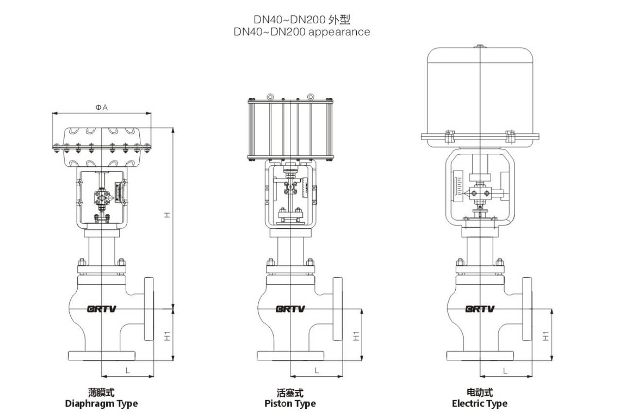
Appearance Dimension
Unit:mm
| NPS | DN | L PN1.6/2.5 (MPa) | H1 | H (Normal Temperature) | H (Mesophilic) | ΦA |
|---|
| 1 1/2 | 40 | 111 | 111 | 555 | 725 | 285 |
| 2 | 50 | 127 | 127 | 555 | 725 | 285 |
| 2 1/2 | 65 | 138 | 138 | 705 | 895 | 360 |
| 3 | 80 | 149 | 149 | 715 | 910 | 360 |
| 4 | 100 | 176 | 176 | 755 | 1005 | 360 |
| 5 | 125 | 196 | 196 | 995 | 1290 | 360 |
| 6 | 150 | 225 | 225 | 955 | 1290 | 470 |
| 8 | 200 | 271 | 271 | 1405 | 1670 | 470 |
Manufacturing Process
Step 1: Order and Design
According to the customer’s working conditions, including pressure, temperature, flow capacity, leakage class, and connection standard, the single seat angle type control valve is designed and confirmed.
Material selection for body, trim, seat, stem, and actuator is finalized, and production drawings are released for manufacturing.
Step 2: Forging & Casting
The valve body and bonnet of the single seat angle type control valve are produced by casting or forging according to the design and pressure rating requirements.
After forming, the raw blanks are inspected for surface quality, dimensions, and internal defects to ensure they meet production standards.
Step 3: Machining
All main components are machined precisely, including valve body, seat ring, plug, stem, bonnet, and flange faces.
For the single seat angle type control valve, special attention is paid to the angle body flow passage, seat sealing surface, and stem guiding parts to ensure accurate control performance and tight shut-off.
Step 4: Assembly
After machining and cleaning, all parts are assembled in sequence, including trim installation, stem connection, packing assembly, bonnet fastening, and actuator mounting.
During assembly of the single seat angle type control valve, the alignment between plug and seat must be carefully adjusted to guarantee stable movement and reliable sealing.
Step 5: Testing & Quality Assurance
Each single seat angle type control valve undergoes strict inspection and testing, such as pressure test, leakage test, stroke calibration, and actuator performance test.
Quality control is carried out throughout the whole process to ensure the valve meets technical specifications and factory standards.
Step 6: Painting and Finishing
After final inspection, the external surface is cleaned, painted, and marked according to order requirements.
Nameplate, flow direction mark, model information, and packing protection are completed before shipment.
Applications
The single seat angle control valve combines the advantages of a single-seat valve, such as good sealing performance and low leakage, with the characteristics of an angular structure, including simple flow path, low resistance, and few dead corners. It is mainly applicable to control scenarios involving high viscosity, suspended particles, or media prone to crystallization. It can effectively reduce clogging and material accumulation. It is also commonly used in high-pressure difference and situations prone to flash evaporation or cavitation to reduce the erosion of the medium on the valve body. Moreover, due to its excellent sealing performance, it is particularly suitable for process operations with strict requirements for leakage control and where the loss of the medium needs to be minimized.
These valves are widely used in:
Agriculture and Irrigation
Factory Environment
Why Choose Us
Superior Quality

Our valves are manufactured using premium materials and undergo rigorous quality testing to ensure reliable performance in demanding industrial applications.
Advanced Technology

Equipped with state-of-the-art CNC machining centers and precision manufacturing equipment, we deliver valves with exceptional accuracy and consistency.
Competitive Pricing

Through optimized manufacturing processes and bulk material procurement, we offer high-quality valves at competitive prices without compromising on quality.
Expert Support

Our experienced technical team provides comprehensive support from product selection to after-sales service, ensuring optimal valve performance for your specific application.