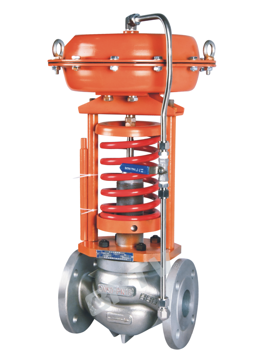
Self-operated Pressure Control Valve
Self-operated Pressure Control Valve adopts external pressure structure, which can automatically adjust and stabilize the pressure depending on the pressure change of the medium itself. It is suitable for liquid, steam, non–corrosive gas and low–viscosity liquid with nominal diameter DN100, P1=1.0MPa, P2=15KPa, pressure reduction ratio is =10, =1.25.
This series is divided into two types: valve rear type ZZYP–B and valve front type ZZYP–K.
Standard Specifications
| Manner | Fluid Pressure Balance Type Trim |
|---|
| Nominal Diameter | 15, 20, 25, 40, 50, 65, 80, 100 mm |
| Nominal Pressure | ANSI Class 150, 300; JIS 10K, 20K; PN 1.6, 4.0 MPa |
| Type of Connection | Flange Type (JIS B2201-1984; JB/T79.1-94; ANSI B16.5-2009; HG20592-2009; HG20615-2009) |
| Trim Material / Trim Treatment | Operating temperature and pressure range depend on various material combinations |
| Body and Bonnet Material | SCHP2/WCB, SCS13A/CF8, SCS14A/CF8M; operating temperature and pressure range depend on material |
| Packing | V-Type PTFE Packing, Graphite Packing |
| Gasket | Asbestos-Free Rubber Sheet |
Rated Kv Value
| Nominal Diameter (DN) | 15 | 20 | 25 | 32 | 40 | 50 | 65 | 80 | 100 |
|---|
| Rated Flow Cv Value (Kv) | 5 | 7 | 11 | 20 | 30 | 48 | 75 | 120 | 190 |
| Rated Stroke (mm) | 8 | 8 | 8 | 10 | 10 | 14 | 20 | 20 | 25 |
| Range of Pressure Segment (kPa) | colspan=9: 15 ~ 50, 40 ~ 80, 60 ~ 100, 80 ~ 140, 120 ~ 180, 160 ~ 220, 200 ~ 260, 240 ~ 300, 280 ~ 350, 300 ~ 400, 380 ~ 450, 430 ~ 500, 480 ~ 560, 540 ~ 620, 600 ~ 700, 680 ~ 800, 780 ~ 900, 880 ~ 1000 | | | | | | | | |
Note: Rated Kv Can Also Choose 0.12, 0.2, 0.3, 0.5, 0.8, 1.2, 2.0, 3.2
Actuator
| Item | Diaphragm Type | Cylinder Type |
|---|
| Diaphragm / Piston Material | Nitrile Rubber | Aluminum Alloy |
| Service | Regulation | Regulation |
| Connector | M16 × 1.5 | M16 × 1.5 |
| Minimum Differential Pressure | Δp ≥ 0.04 MPa | Δp ≥ 0.04 MPa |
| Pressure Adjustable Range | ≤ 0.5 MPa | 0.5 ~ 1.0 MPa |
| Operating Temperature | -5 ~ 350 °C | -5 ~ 350 °C |
| Standard Coating Color | Grey | Grey |
Performance and Model Selection Parameter Table
| Nominal Diameter (DN) | 20 | 25 | 32 | 40 | 50 | 65 | 80 | 100 | 125 | 150 | 200 | 250 | 300 |
|---|
| Rated Flow Cv Value (Kv) | 7 | 11 | 20 | 30 | 48 | 75 | 120 | 190 | 300 | 480 | 760 | 1100 | 1750 |
| Rated Stroke (mm) | 8 | 10 | 14 | 20 | 25 | 40 | 50 | 60 | 70 | | | | |
| Nominal Pressure | colspan=13: PN16, PN40, PN64; CLASS150LB–300LB | | | | | | | | | | | | |
| Adjusting Range of Pressure Difference (kPa) | colspan=13: 15–50, 40–80, 60–140, 120–220, 160–220, 200–260, 240–300, 280–350, 330–400, 380–450, 480–560, 540–620, 600–700, 680–780, 780–900, 880–1000, 950–1500, 1000–2500 | | | | | | | | | | | | |
| Flow Characteristic | colspan=13: Quick-opening | | | | | | | | | | | | |
| Accuracy of Adjustment | colspan=13: ±5–10% | | | | | | | | | | | | |
| Operating Temperature | colspan=13: −40 °C (no condenser) ≤200 °C; with condenser ≤350 °C | | | | | | | | | | | | |
| Allowable Leakage (Soft Seat, L/h) | 0.15 | 0.3 | 0.45 | 0.6 | 0.9 | 1.7 | 4 | 6.75 | 11.1 | 16 | | | |
| Pressure Reducing Ratio (Max) | colspan=13: 10 | | | | | | | | | | | | |
| Pressure Reducing Ratio (Min) | colspan=13: 1.25 | | | | | | | | | | | | |
| Minimum Upstream Pressure (kPa) | 30 | 50 | 100 | 150 | 200 | 250 | 300 | 350 | 400 | | | | |
| Downstream Pressure Range (kPa) | 15–24 | 15–40 | 15–80 | 15–120 | 20–160 | 25–200 | 30–240 | 35–280 | 40–320 | | | | |
| Upstream Pressure (kPa) | 450 | 500 | 550 | 600 | 650 | 700 | 750 | 800 | 850 | | | | |
| Downstream Pressure (kPa) | 45–360 | 50–400 | 55–440 | 60–480 | 65–520 | 70–560 | 75–600 | 80–640 | 85–680 | | | | |
| Upstream Pressure (kPa) | 900 | 950 | 1000 | 1250 | 1500 | 2000 | 2500 | 3000 | | | | | |
| Downstream Pressure (kPa) | 90–720 | 95–760 | 100–800 | 125–1000 | 150–1200 | 200–1600 | 250–2000 | 300–2400 | | | | | |
The Material of Valve and Components, Range of Using Temperature
Body Material: Carbon Steel
| Item | Specification |
|---|
| Body Material | SCHP2 / A216-WCB |
| Core | SUS304 |
| Seat | SUS304 |
| Bellows | SUS304 |
| Diaphragm | Nitrile Rubber |
| Piston | Aluminum Alloy |
| Gasket | Asbestos-Free Rubber Sheet |
| Operating Temperature | -5 ~ +350 °C |
Body Material: Stainless Steel
| Item | Specification |
|---|
| Body Material | SCS13A / CF8, SCS14A / CF8M |
| Core | SUS316 |
| Seat | SUS316 |
| Bellows | SUS316 |
| Diaphragm | Nitrile Rubber |
| Piston | Aluminum Alloy |
| Gasket | Asbestos-Free Rubber Sheet |
| Operating Temperature | -5 ~ +350 °C |
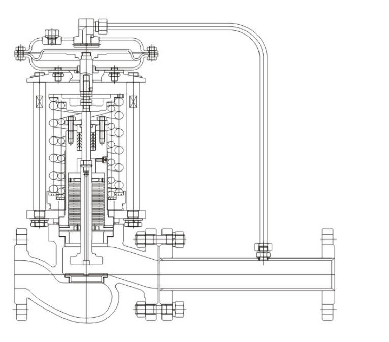
Outline Drawing
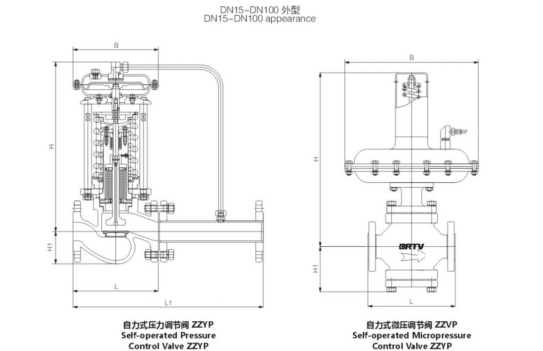
Main Outline and weight
Unit:mm
| Item | 15 | 20 | 25 | 32 | 40 | 50 | 65 | 80 | 100 |
|---|
| Nominal Diameter (DN) | 15 | 20 | 25 | 32 | 40 | 50 | 65 | 80 | 100 |
| Length of Flange Connection Tube (L1) | 383 | 383 | 383 | 512 | 512 | 603 | 862 | 862 | 1023 |
| Flange End Face to Face (L) | 150 | 150 | 160 | 180 | 200 | 230 | 290 | 310 | 350 |
| H1 | 32 | 32 | 36 | 58 | 58 | 62 | 75 | 85 | 105 |
| Range of Pressure Regulation (kPa) 15–140 H | 475 | 475 | 475 | 520 | 520 | 540 | 710 | 710 | 780 |
| Range of Pressure Regulation (kPa) 15–140 B | 280 | 280 | 280 | 310 | 310 | 310 | 310 | 310 | 310 |
| Range of Pressure Regulation (kPa) 120–300 H | 455 | 455 | 455 | 500 | 500 | 520 | 690 | 690 | 760 |
| Range of Pressure Regulation (kPa) 120–300 B | 195 | 195 | 195 | 230 | 230 | 230 | 230 | 230 | 230 |
| Range of Pressure Regulation (kPa) 280–500 H | 450 | 450 | 450 | 490 | 490 | 510 | 680 | 680 | 750 |
| Range of Pressure Regulation (kPa) 280–500 B | 176 | 176 | 176 | 176 | 176 | 176 | 200 | 200 | 200 |
| Range of Pressure Regulation (kPa) 480–1000 H | 445 | 445 | 445 | 480 | 480 | 480 | 670 | 670 | 740 |
| Range of Pressure Regulation (kPa) 480–1000 B | 176 | 176 | 176 | 176 | 176 | 176 | 200 | 200 | 200 |
| Weight (~kg) | 26 | 26 | 26 | 37 | 37 | 42 | 72 | 90 | 114 |
| Joint Thread of Connecting Pipe | colspan=9: M16 × 1.5 | | | | | | | | |
Manufacturing Process
Step 1: Order and Design
Confirm the working conditions of the self-operated pressure control valve, including medium, pressure range, temperature, connection type, and body material. Based on customer requirements, prepare drawings, select suitable diaphragm, spring, trim, and actuator structure, and finalize the production plan.
Step 2: Forging & Casting
The main pressure-bearing parts such as valve body, bonnet, and internal components of the self-operated pressure control valve are produced by forging or casting according to the material specification. Common materials include WCB, CF8, CF8M, and stainless steel. After forming, the raw parts are cleaned and inspected for surface quality.
Step 3: Machining
All key components are machined with CNC lathes, drilling machines, and milling equipment. For the self-operated pressure control valve, machining includes body cavity, flange faces, seat pocket, stem guide surfaces, and threaded parts, ensuring dimensional accuracy and sealing performance.
Step 4: Assembly
After machining, all parts are cleaned and assembled in sequence. The valve trim, spring, diaphragm, actuator, tubing, and fasteners are installed carefully to complete the self-operated pressure control valve assembly. During this process, spring preload and set pressure range are adjusted according to design requirements.
Step 5: Testing & Quality Assurance
Each self-operated pressure control valve must undergo pressure testing, leakage testing, action testing, and set-point verification before delivery. The inspection team also checks appearance, nameplate data, assembly quality, and functional stability to ensure the valve meets quality standards.
Step 6: Painting and Finishing
After final inspection, the valve surface is cleaned, anti-rust treated, and painted if required. Then the product is attached with nameplate, protective covers, and packaging marks before packing and shipment.
Applications
Suitable for the control of liquid, gas and steam media in fields such as petroleum, chemical engineering, power and heating systems.
These valves are widely used in:
Agriculture and Irrigation
Factory Environment
Why Choose Us
Superior Quality

Our valves are manufactured using premium materials and undergo rigorous quality testing to ensure reliable performance in demanding industrial applications.
Advanced Technology

Equipped with state-of-the-art CNC machining centers and precision manufacturing equipment, we deliver valves with exceptional accuracy and consistency.
Competitive Pricing

Through optimized manufacturing processes and bulk material procurement, we offer high-quality valves at competitive prices without compromising on quality.
Expert Support

Our experienced technical team provides comprehensive support from product selection to after-sales service, ensuring optimal valve performance for your specific application.