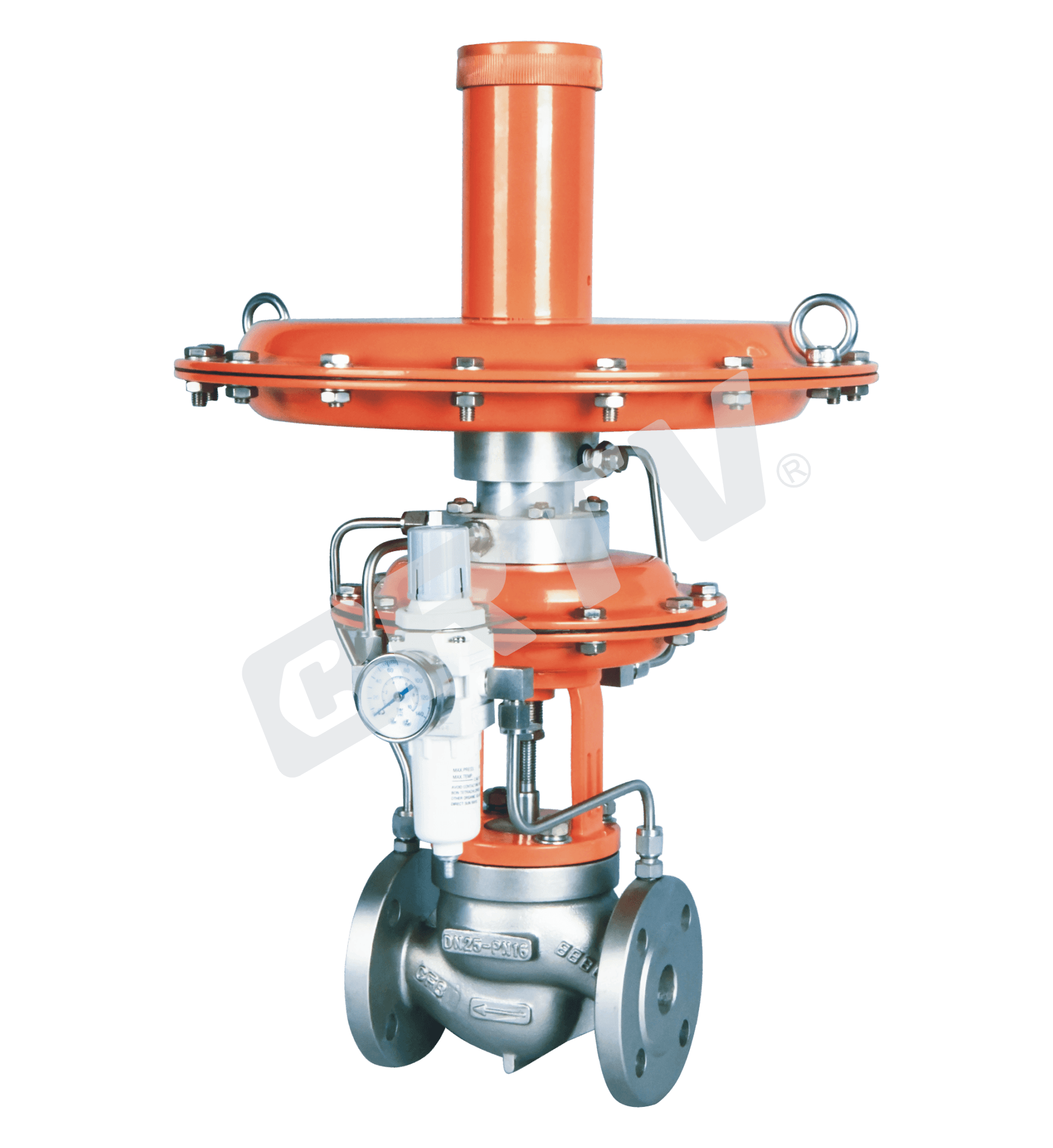
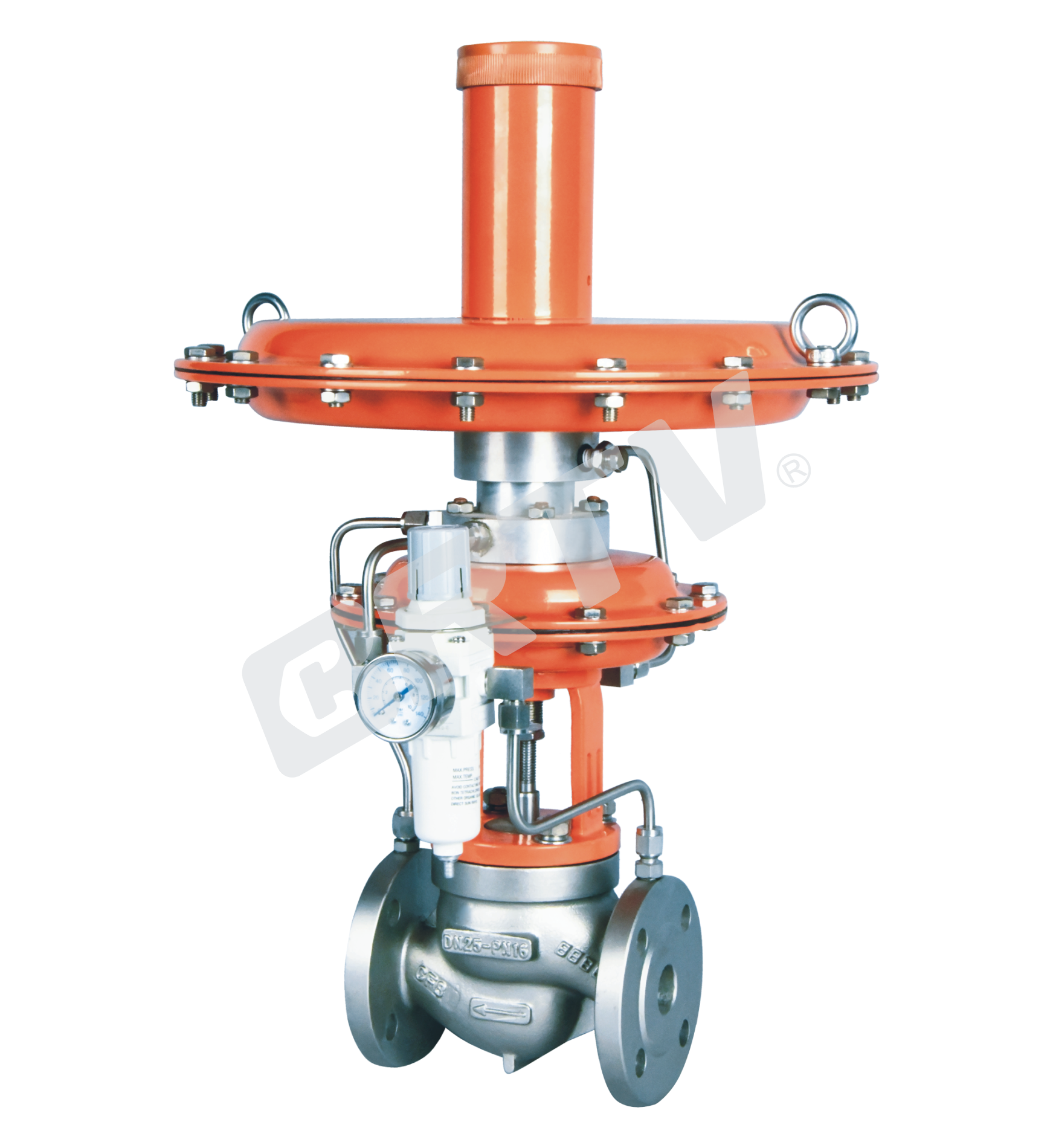
Pilot Operated Pressure Control Valve
Pilot Operated Pressure Control Valve (Nitrogen Sealed), which is an energy–saving pressure control valve that does not need external energy and can use the pressure change of the medium itself to automatically adjust and stabilize the pressure after the valve is set. The valve pressure setting is realized on the command, which is convenient and fast. The pressure setting value can be adjusted at will in operation. High control accuracy, it is suitable for control switch, cannot continuous control with high precision requirements when valve P is less than 1MPa, after the valve < 10KPa.
It is widely used in chemical, petroleum, metallurgy, electric power, textile and other industrial sectors as automatic regulation of the production process. Especially, it is suitable for nitrogen seal system of storage tank. The valve pressure reduction ratio: 1:100. This series has only one kind of rear valve ZZYVP–16B.
Standard Specifications
| Manner | Fluid Pressure Balance Type Trim |
|---|
| Nominal Diameter | 20, 25, 40, 50, 65, 80, 100, 150 mm |
| Nominal Pressure | PN 1.6 MPa; ANSI Class 150; JIS 10K |
| Type of Connection | Flange (JIS B2201-1984, JB/T79.1-94, ANSI B16.5-2009, HG20592-2009, HG20615-2009) |
| Trim Material / Trim Treatment | The operating temperature and pressure range depend on the combination of trim materials |
| Body and Bonnet Material | SCPH2/WCB, SCS13A/CF8, SCS14A/CF8M — operating temperature and pressure range depend on material |
| Packing | V-Type PTFE packing, Graphite packing |
| Gasket | Asbestos Free Rubber Sheet |
Specified Kv Value
| Item | 20 | 25 | 40 | 50 | 80 | 100 | 150 |
|---|
| Rated Flow Cv Value (Kv) | 6 | 15 | 20 | 25 | 32 | 40 | 50 |
| Rated Stroke (mm) | 0.32 | 5 | 8 | 11 | 20 | 30 | 48 |
| Range of Pressure Segment (KPa) | colspan=7 0.10.5, 0.45.0, 4.0~12.0 | | | | | | |
Actuator
| Type | Diaphragm Type |
|---|
| Diaphragm Material | Nitrile Rubber |
| Available Area of Actuator (cm²) | 100, 200, 280, 400 |
| Service | Regulation |
| Connector | M10×1 / M16×1 |
| Pressure Adjustable Range | 0.1–0.5, 0.4–5.0, 4.0–12.0 |
| Operating Temperature | -5 ~ +100 °C |
| Standard Coating Color | Grey |
Pressure Adjustable Range
| Pressure Adjustable Range (KPa) | Effective Area of the Command Membrane Chamber (cm²) | Effective Area of the Membrane Chamber of the Actuator (cm²) | Use Valve Diameter (mm) |
|---|
| 0.1–0.5 | 1200 | 100 | 20–32 |
| 0.4–5.0 | 600 | 100 | 20–32 |
| 4.0–12.0 | 400 | 100 | 20–32 |
| 0.1–0.5 | 1200 | 200 | 40–50 |
| 0.4–5.0 | 600 | 200 | 40–50 |
| 4.0–12.0 | 400 | 200 | 40–50 |
| 0.1–0.5 | 1200 | 400 | 65–100 |
| 0.4–5.0 | 600 | 400 | 65–100 |
| 4.0–12.0 | 400 | 400 | 65–100 |
| 0.1–0.5 | 1200 | 600 | 125–150 |
| 0.4–5.0 | 600 | 600 | 125–150 |
| 4.0–12.0 | 400 | 600 | 125–150 |
The Material of Valve and Components, Range of Using Temperature · Allowable Leakage of Seat
Body Material: Carbon Steel
| Body Material | SCPH2 / WCB |
|---|
| Core | SUS304 |
| Seat | SUS304 |
| Bellows | SUS304 |
| Diaphragm | Nitrile Rubber |
| Piston | Aluminum Alloy |
| Gasket | Asbestos Free Rubber Sheet |
| Operating Temperature | -5 ~ +350 °C |
Body Material: Stainless Steel
| Body Material | SCS13A / CF8, SCS14A / CF8M |
|---|
| Core | SUS316 |
| Seat | SUS316 |
| Bellows | SUS316 |
| Diaphragm | Nitrile rubber |
| Piston | Aluminum alloy |
| Gasket | Asbestos free rubber sheet |
| Operating Temperature | -5 ~ +100 °C |
Valve Back Type (Diaphragm Type Actuator)
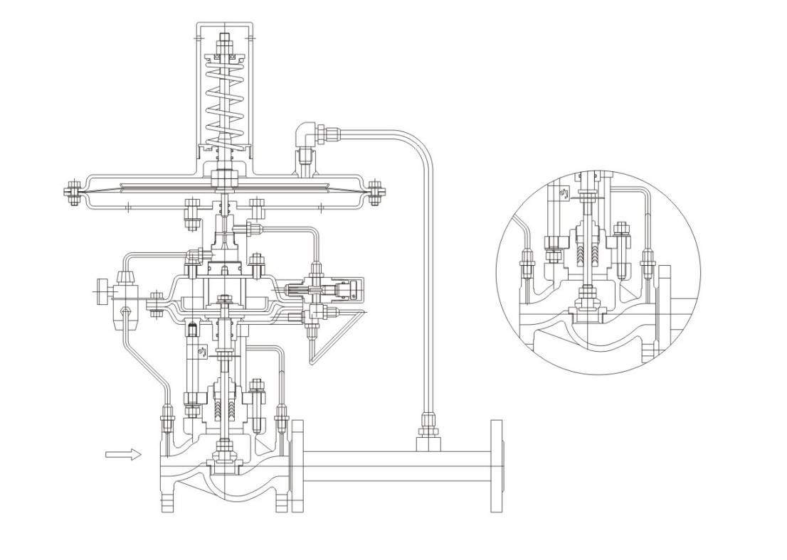
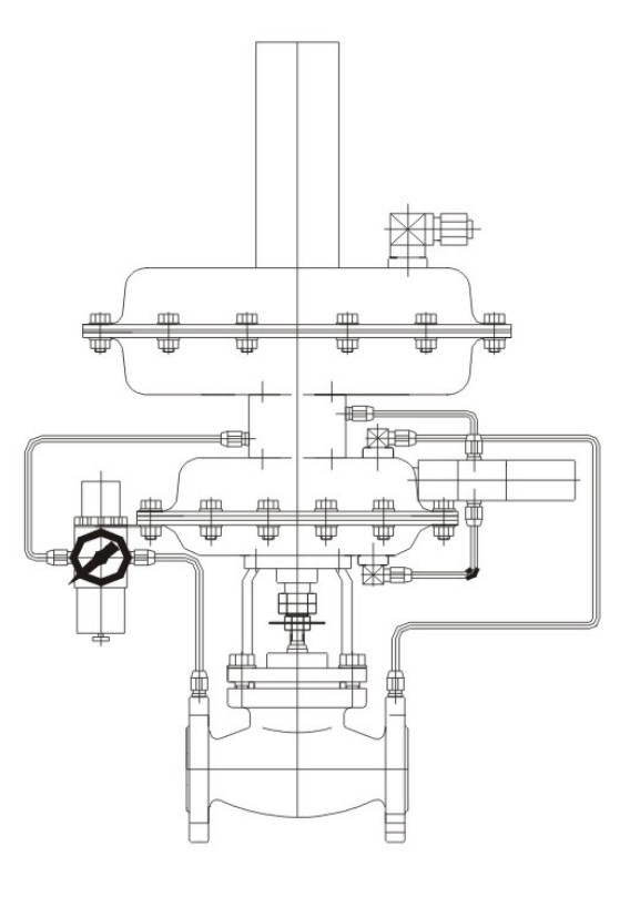
The Structure and Principle of Valve
Pilot Operated Pressure Control Valve (Nitrogen Sealed) is composed of four parts: the conductor, the control valve, the actuator and the valve after the take–over.
Principle:
The medium enters the valve body in the direction of arrow as shown, and is divided into two way. One way is that the pressure after the pressure relief through the filter depressor is introduced into the conductor. The other way is that the medium goes through the spool, seat, and throttle after the pressure flow to the back of the valve. Then it goes through the pressure pipe into the command actuator. When the pressure behind the valve is higher than the set pressure, the pressure acting on the effective surface of the command film will generate a thrust to drive the command spool to close, and cut off the pressure introduced into the film chamber of the main valve actuator, so that the main valve spool will close and the pressure behind the valve will decrease accordingly.
When the pressure behind the valve is lower than the set value, due to the reaction force of the main spring of the conductor to open the command spool, the pressure in front of the valve is introduced into the film chamber of the main valve actuator to generate thrust, which causes the main valve trim to open and the pressure behind the valve to rise accordingly. After reciprocating, we should maintain the pressure behind the valve as the set value.
Outline Drawing
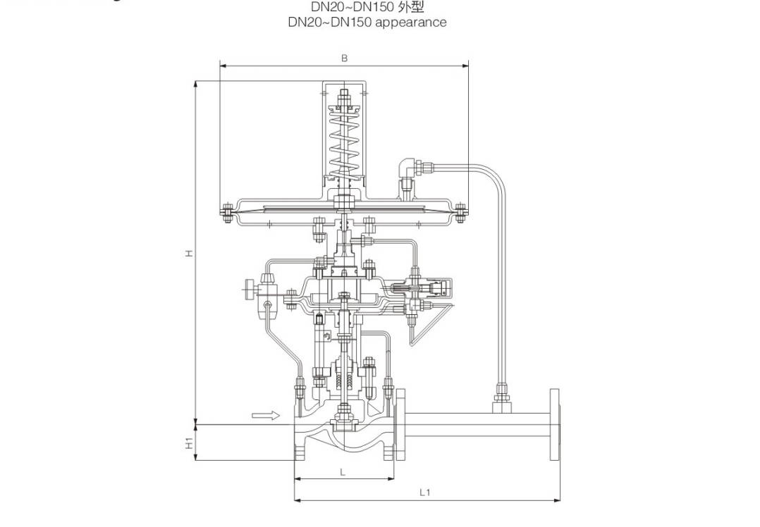
Appearance Dimension
Unit:mm
| Nominal Diameter (mm) | L | L1 | H1 | H (B=1200 cm²) 0.1–0.5 KPa | H (B=600 cm²) 0.4–5.0 KPa | H (B=400 cm²) 0.5–7.0 KPa |
|---|
| 20 | 150 | 383 | 53 | 605 | 554 | 554 |
| 25 | 160 | 383 | 58 | 605 | 554 | 554 |
| 32 | 180 | 512 | 70 | 615 | 564 | 564 |
| 40 | 200 | 512 | 75 | 640 | 589 | 589 |
| 50 | 230 | 603 | 83 | 655 | 604 | 604 |
| 65 | 290 | 862 | 93 | 722 | 671 | 671 |
| 80 | 310 | 862 | 100 | 738 | 687 | 687 |
| 100 | 350 | 1023 | 110 | 755 | 704 | 704 |
| 125 | 400 | 1380 | 125 | 918 | 867 | 867 |
| 150 | 480 | 1380 | 143 | 1125 | 974 | 974 |
Manufacturing Process
Step 1: Order and Design
Based on the operating conditions parameters provided by the customer, such as pipe diameter, pressure grade, medium type, temperature range and connection method, the structural form, valve body material, internal component configuration and actuator parameters of the pilot operated pressure control valve are confirmed. After the completion of the drawing, BOM list and production process requirements confirmation, the production order is issued.
Step 2: Forging & Casting
According to the design requirements, the pressure-bearing components such as the valve body and valve cover are to be forged or cast. The blank of the valve body for the Pilot operated pressure control valve must ensure sufficient strength, density and size tolerance, and the castings or forgings need to undergo appearance inspection to prevent defects such as air holes, sand holes and cracks from affecting the subsequent processing.
Step 3: Machining
Carry out precise mechanical processing on the valve body, valve seat, valve stem, diaphragm cover, connection joints and related components of the control instrument. For the pilot operated pressure control valve, during this stage, the focus is on controlling the accuracy of the sealing surfaces, the accuracy of the threads, the coaxiality and the mating dimensions, in order to ensure that the valve has sensitive pressure regulation, stable operation and reliable sealing.
Step 4: Assembly
After the processed and inspected parts are cleaned and deburred, they proceed to the assembly process. According to the process requirements, the main valve, actuator, diaphragm assembly, spring assembly, pressure guiding pipeline and accessories are assembled in sequence. The assembly process of the Pilot operated pressure control valve requires special attention to ensuring the smoothness of the pressure guiding channel, firm connections, and proper installation of all seals.
Step 5: Testing & Quality Assurance
After assembly is completed, conduct pressure tests, seal tests, operation performance tests and pressure regulation accuracy tests on the pilot-operated pressure control valve to confirm its smooth opening and closing, accurate pressure stabilization, and no internal or external leakage. At the same time, complete size re-inspection, appearance inspection and relevant record archiving in accordance with quality requirements to ensure that the product meets the factory standards.
Step 6: Painting and Finishing
After passing the test, the surface of the valve should be cleaned, rust-prevented, primed and painted. Labels, tags and protective packaging should also be installed as per requirements. For pilot-operated pressure control valves, before leaving the factory, the appearance integrity and completeness of accessories need to be checked to ensure convenient and safe transportation and on-site installation.
Applications
It is mainly applied to the nitrogen supply and exhaust systems of nitrogen packaging devices, suitable for working conditions with high pressure before the valve (0.1 - 0.8 MPa) and extremely low pressure after the valve (0.5 - 100 kPa), especially for scenarios requiring precise control of micro-pressure at the 50mm water column level.
These valves are widely used in:
Agriculture and Irrigation
Factory Environment
Why Choose Us
Superior Quality

Our valves are manufactured using premium materials and undergo rigorous quality testing to ensure reliable performance in demanding industrial applications.
Advanced Technology

Equipped with state-of-the-art CNC machining centers and precision manufacturing equipment, we deliver valves with exceptional accuracy and consistency.
Competitive Pricing

Through optimized manufacturing processes and bulk material procurement, we offer high-quality valves at competitive prices without compromising on quality.
Expert Support

Our experienced technical team provides comprehensive support from product selection to after-sales service, ensuring optimal valve performance for your specific application.