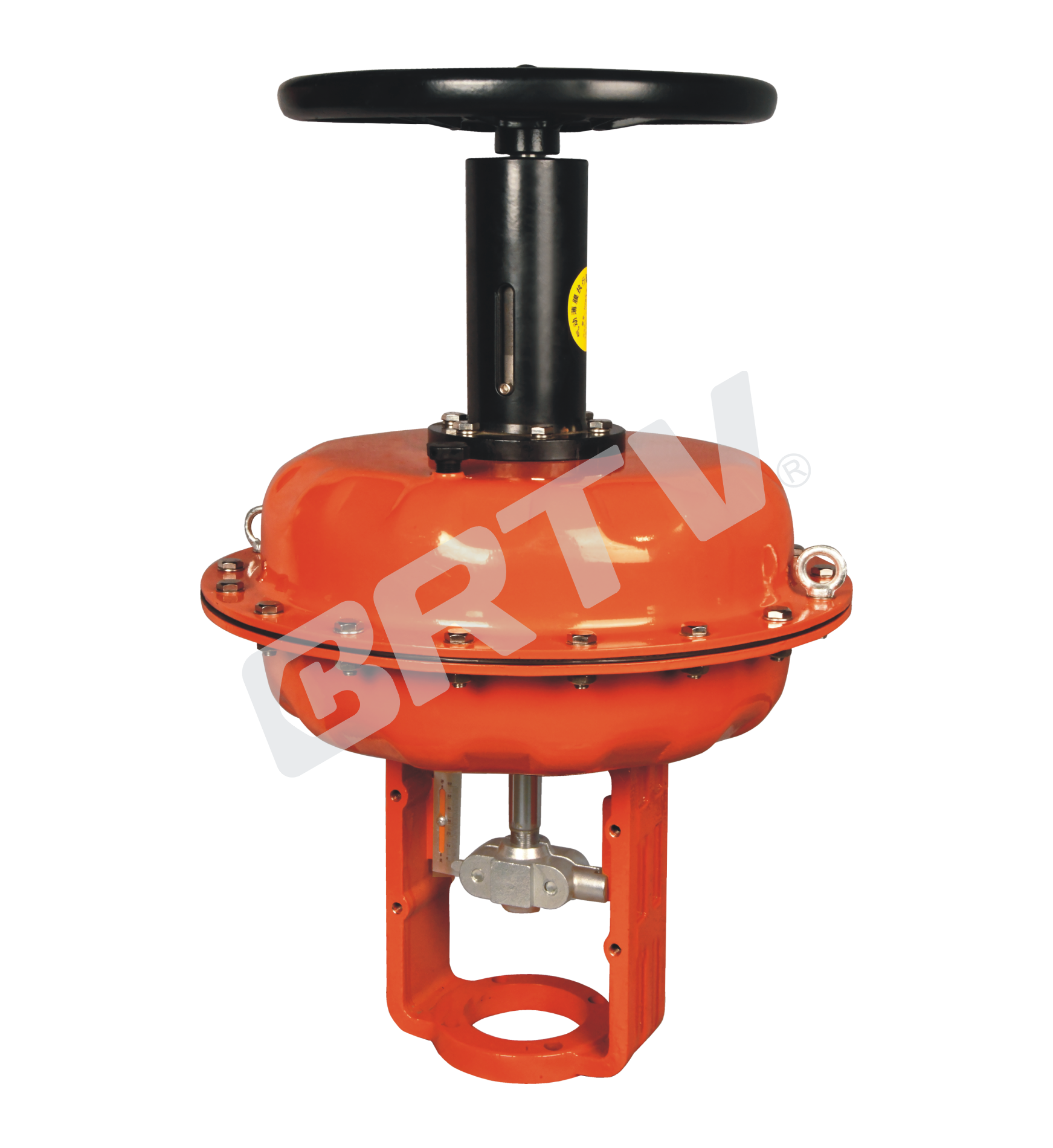
Multi-spring Pneumatic Diaphragm Actuator
Multi-spring Pneumatic Diaphragm Actuator is a new pneumatic diaphragm actuator, which is designed and developed for the problems of the old ZMA/B single–spring pneumatic diaphragm actuator, such as large size, bulky, reliable deep corrugated diaphragm, etc. The shape of the diaphragm is relatively complex, and special pressing technology is adopted to make the blasting intensity reach more than 2kg/cm². Multi–spring form improves the spring manufacturing process, and it is advantageous to the different spring range combination. Zeroing improves linearity. Surface treatment with high fastness and corrosion resistance, and adopts epoxy electrostatic powder spraying.
It has the advantages of uniform force, good stability, small size and light weight. Besides, it can be equipped with pneumatic, electric valve positioner and air filter accessories. It can also be equipped with ZPXS, ZDXS type light side mount, and top mount manual operation mechanism.
Actuator
| Item | ZJHA/B-11 | ZJHA/B-22 | ZJHA/B-23 | ZJHA/B-34 | ZJHA/B-45 | ZJHA/B-56 |
|---|
| Rated Stroke (mm) | 10 | 10, 16 | 16, 25 | 40 | 40, 60 | 100 |
| Active Area (cm²) | 200 | 350 | 350 | 560 | 960 | 1600 |
| Size of Air Connection | M16×1.5 | M16×1.5 | M16×1.5 | M16×1.5 | M16×1.5 | M16×1.5 |
| Air Pressure | colspan=6 0.14, 0.25 MPa | | | | | |
| Ambient Temperature | colspan=6 -30 ~ +6 °C | | | | | |
| Spring Range | colspan=6 20–100 KPa, 40–200 KPa, 80–240 KPa | | | | | |
| Action | colspan=6 ZJHA: Direct action — stem moves down when signal pressure increases. ZJHB: Reverse action — stem moves up when signal pressure increases. | | | | | |
Application Data
1. Flow Characteristics
This product mainly has two kinds of inherent flow characteristics to choose from: straight line and equal percentage. Because of careful design and manufacturing, the accurate flow characteristics of the product are guaranteed, which is in line with the requirements of IEC standard slope method assessment, so as to promote the use of high quality control effect. This flow characteristic is designed according to the adjustable ratio R50. Compared with the product of R30, it expands the possibility of single valve to realize wide load change control and it is more suitable for most systems with low pressure drop ratio between valve and system.
2. Relationship between Working Pressure and Temperature
When selecting the nominal pressure of the control valve in terms of the maximum nominal pressure of the process medium, we must meet the requirements of the medium working temperature. Because the nominal pressure is set according to the strength condition at a certain reference temperature. Once the operating temperature exceeds the reference temperature, the maximum allowable working pressure must be lower than the nominal pressure. Please pay more attention about this point above.
3. Allowable Pressure Difference
When selecting the control valve, in addition to other conditions, we should also consider the thrust angle, that is to say, whether the control valve can operate normally, and whether it can be expressed with characteristic data, which means the allowable pressure difference is higher than the maximum working pressure difference.
In order to improve the degree of standardization, applicability and serialization, the actuator parts and valve parts in the control valve have a set of standard combinations. The allowable differential pressure specified in various combinations can usually be applied to the working differential pressure conditions in general process.
Outline Drawing
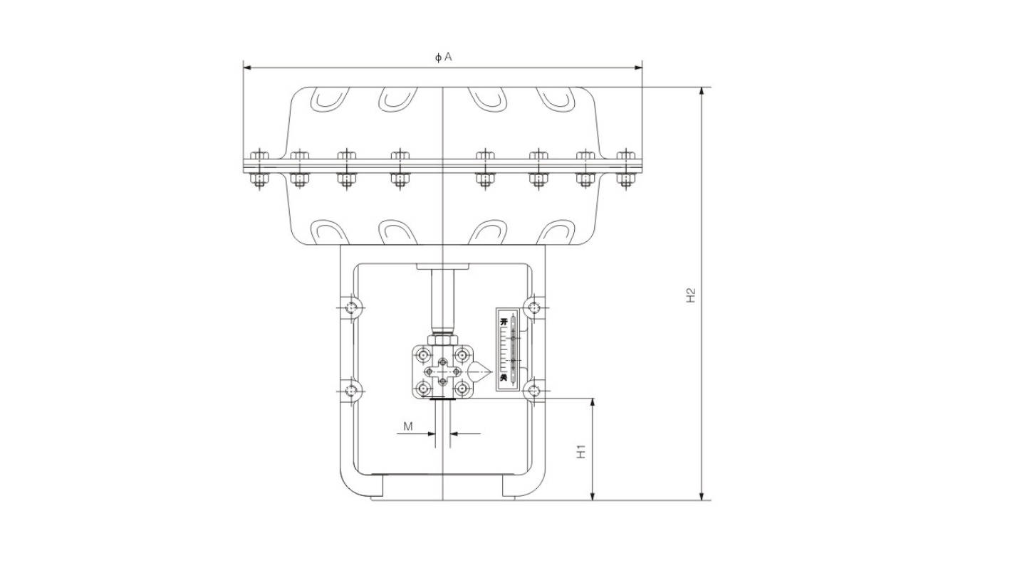
Appearance Dimension
| Model | ΦA (mm) | H1 (mm) | H2 (mm) | Thread Size (M) | Weight (~kg) |
|---|
| ZJHA/B-11 | 265 | 90 | 274 | M8 | 6 |
| ZJHA/B-22 | 285 | 95 | 274 | M10 | 12 |
| ZJHA/B-23 | 285 | 95 | 298 | M12 | 16 |
| ZJHA/B-34 | 365 | 125 | 375 | M12 | 22 |
| ZJHA/B-45 | 480 | 125 | 465 | M16×1.5 | 35 |
| ZJHA/B-56 | 595 | 160 | 666 | M30×2 | 68 |
Manufacturing Process
Step 1: Order and Design
Based on the customer’s requirements for thrust, stroke, air supply pressure, failure mode, and mounting dimensions, the model and structure of the multi-spring pneumatic diaphragm actuator are determined. The engineering team completes the design of drawings, material selection, spring assembly configuration, and technical verification of key components such as the diaphragm and bracket to ensure the actuator meets the operational requirements of the control valve.
Step 2: Forging & Casting
Critical pressure-bearing or structural components of the actuator, such as the top cover, lower diaphragm chamber, and brackets, are formed through casting or forging. For multi-spring pneumatic diaphragm actuators, raw materials must possess excellent strength, toughness, and dimensional stability to ensure precision in subsequent machining and overall assembly performance.
Step 3: Machining
Cast and forged components undergo turning, milling, drilling, tapping, and precision finishing of sealing surfaces to ensure all mating dimensions meet drawing specifications. For multi-spring pneumatic diaphragm actuators, machining accuracy must be strictly controlled for the spring seats, diaphragm clamps, connection points, and guide areas to ensure smooth operation and reliable sealing.
Step 4: Assembly
Assemble the diaphragm chamber, spring assembly, valve stem connector, bracket, and accessories in sequence according to the assembly process, and adjust the preload. During assembly of the multi-spring pneumatic diaphragm actuator, special attention must be paid to the uniformity of force distribution across the springs, the diaphragm’s installation position, and the coaxiality of moving parts to ensure output force and operational sensitivity.
Step 5: Testing & Quality Assurance
After assembly, the multi-spring pneumatic diaphragm actuator undergoes air tightness testing, stroke testing, spring range verification, response testing, and visual inspection. The quality department confirms that the product meets factory release requirements for strength, sealing performance, and operational stability in accordance with relevant standards and inspection specifications.
Step 6: Painting and Finishing
After passing inspection, the outer surface undergoes rust removal, cleaning, spray painting, and marking to enhance the product’s corrosion resistance and aesthetic quality. Finally, nameplate installation, packaging, and shipment preparation are completed to ensure the actuator remains in good condition during transportation and on-site use.
Applications
Primarily used for regulating fluid media in industrial sectors such as chemicals, petroleum, and metallurgy.
These valves are widely used in:
Agriculture and Irrigation
Factory Environment
Why Choose Us
Superior Quality

Our valves are manufactured using premium materials and undergo rigorous quality testing to ensure reliable performance in demanding industrial applications.
Advanced Technology

Equipped with state-of-the-art CNC machining centers and precision manufacturing equipment, we deliver valves with exceptional accuracy and consistency.
Competitive Pricing

Through optimized manufacturing processes and bulk material procurement, we offer high-quality valves at competitive prices without compromising on quality.
Expert Support

Our experienced technical team provides comprehensive support from product selection to after-sales service, ensuring optimal valve performance for your specific application.