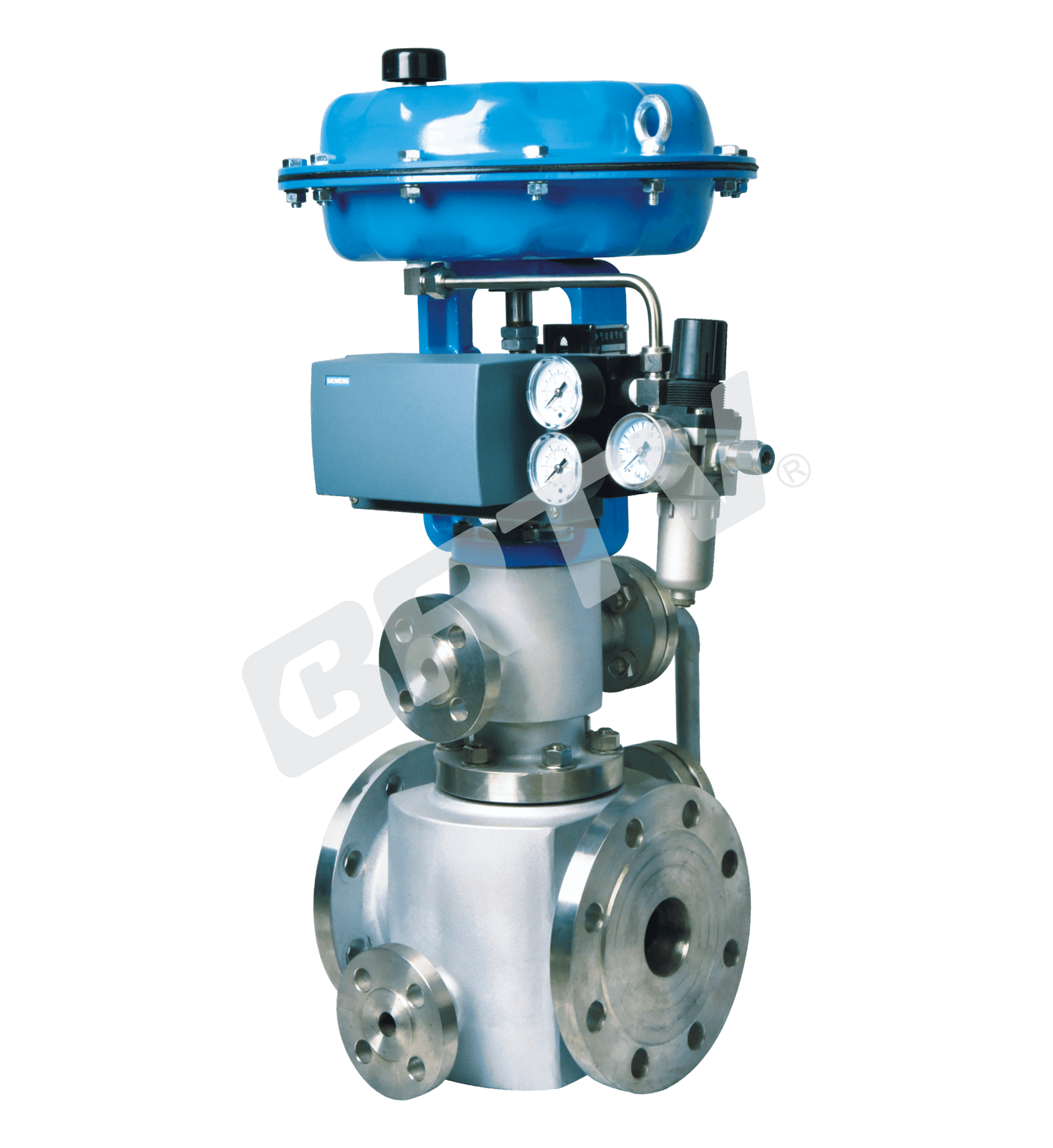
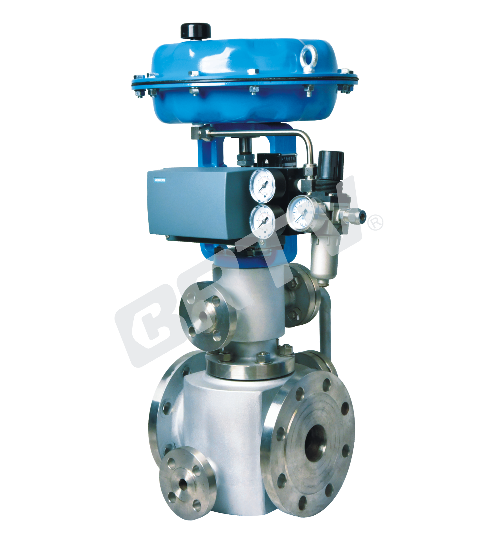
Jacketed Single Seat Control Valve
Jacketed Single Seat Control Valve is suitable for the occasion of heat preservation. When the crystallization temperature of the process medium is lower than the ambient temperature or the fluid temperature decreases, resulting in increased viscosity or solidification of the fluid.
At this moment, in the valve body and valve cover on the steam insulation jacket device, the process medium to meet the needs of process control. The amount of leakage of the control valve conforms to the ANSI FCI collateral 2–2006 standard. It is equipped with multiple spring diaphragm actuator, compact structure, large output force. The product conforms to GB/T4213–2008 standard.
Standard Specifications
| Item | Specification |
|---|
| Manner | Straight Through Cast Ball Valve |
| Nominal Diameter | 40, 50, 65, 80, 100, 150 mm |
| Nominal Pressure | ANSI Class 150, 300; JIS 10K, 16K, 20K; PN 1.6, 4.0 MPa |
| Type of Connection | Flange Type: FF, RF, RJ, TG, MFM |
| Body and Bonnet Material | SCPH2/WCB, SCPH21/WC6, SCS13A/CF8, SCS14A/CF8M, SCS16A/CF3M, Ti (Operating temperature and pressure range depend on material) |
| Bonnet Manner | Elongation Type I (E.I): −17 ~ +566 °C |
| Gland Manner | Screw Fastening Type |
| Packing | V-Type PTFE Packing, Graphite Packing |
| Gasket | Plain Type, Zigzag Type (Materials: Carbon Steel, SUS304, SUS316, SUS316L) and other alloys |
| Surface Coating | Blue (Epoxy). When the valve body material is stainless steel, coating may not be applied |
Flange Standard: JIS B2201–1984, JB/T79.1–94 (PN1.6MPA), JB/T79.2–94 (PN4.0, 6.4MPA), ANSI B16.5–2009, HG20592–2009, HG20615–2009
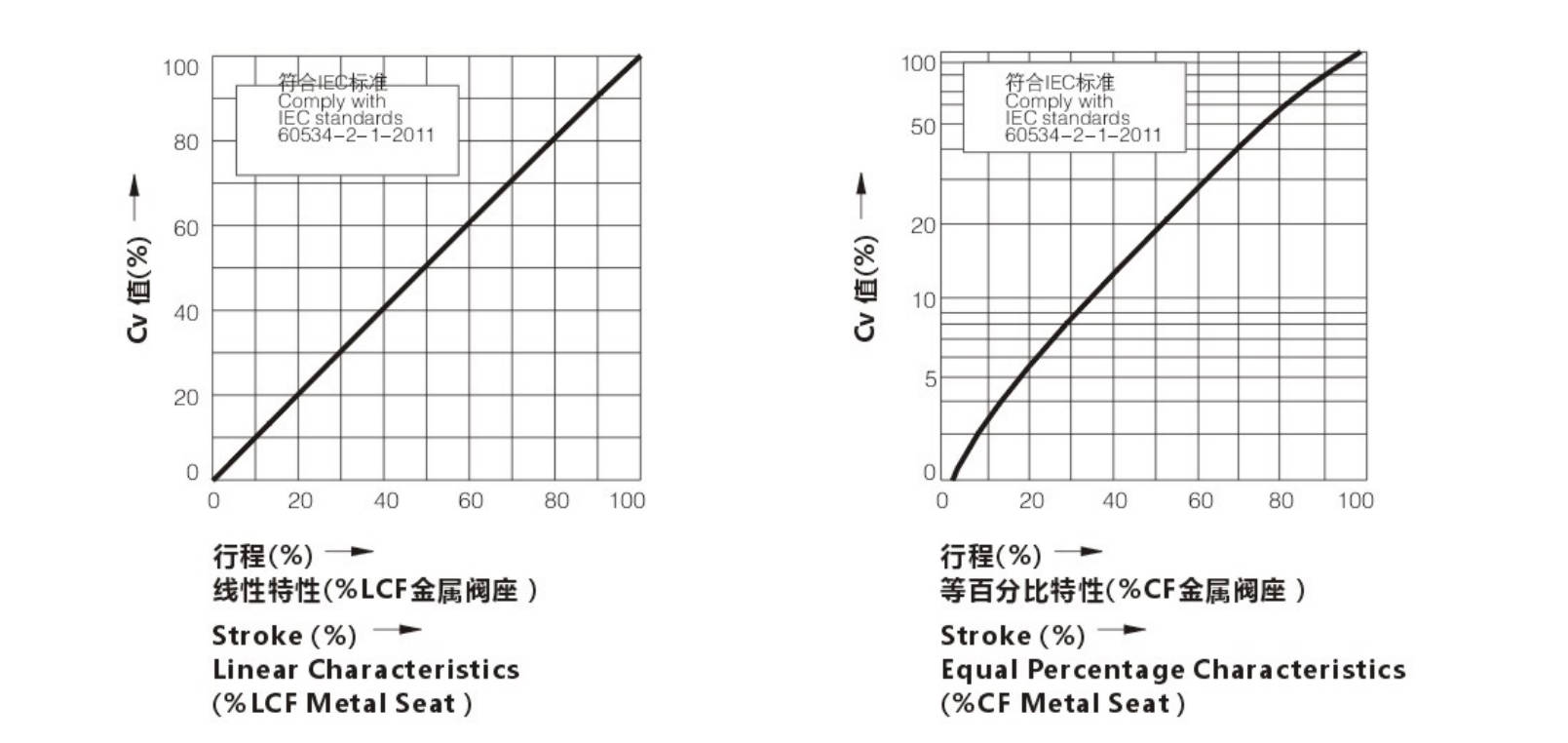
Cv Value and Stroke
| Nominal Diameter | 40 | 50 | 65 | 80 | 100 | 150 |
|---|
| Seat Diameter | Cv=4.0 | Cv=6.3, 25 | 32, 25 | 32, 40 | 50, 40 | 65, 80, 100 |
| Rated Cv | 4.0, 6.3, 12 | 6.3, 12, 21 | 12, 21, 30 | 21, 30, 50 | 30, 50, 85 | 85, 125, 200 |
| Rated Stroke | 25 | 25 | 25 | 40 | 40 | 60 |
J – semi–heat preservation of body | B – heat preservation of body
Actuator
| Item | Pneumatic Diaphragm Type (ZJHA/B) | Pneumatic Cylinder Piston Type – Single Action (ZTCLS) | Pneumatic Cylinder Piston Type – Double Action (ZTCL) | Electronic Type (381 Series) | Intelligent Type (ZM Series) |
|---|
| Structure | Multiple Springs Type | Single Action | Double Action | Electronic | Intelligent |
| Service | Regulation | Regulation | Regulation | Regulation | Regulation |
| Supply Gas Pressure / Supply Voltage | 140–200 kPa / 160–200 kPa / 280–240 kPa / 400–600 kPa | Supply Gas Pressure: 400–700 kPa | Supply Gas Pressure: 400–700 kPa | Voltage: 220/380V 50Hz; Input Signal: 4–20 mA DC | Voltage: 220/380V 50Hz; Input Signal: 4–20 mA DC |
| Connector | Air Piping: RC1/4 | Air Piping: G1/8, G1/4, G1/2, G3/8 | Air Piping: G1/8, G1/4, G1/2, G3/8 | Wiring: PG13.5 | Wiring: PG13.5 |
| Positive Action | Adding Pressure → Valve Will Be Closed | Adding Pressure → Valve Will Be Closed | Adding Pressure → Valve Will Be Closed | Input Signal → Valve Will Be Closed | Input Signal → Valve Will Be Closed |
| Negative Action | Adding Pressure → Valve Will Be Opened | Adding Pressure → Valve Will Be Opened | Adding Pressure → Valve Will Be Opened | Input Signal → Valve Will Be Opened | Input Signal → Valve Will Be Opened |
| Hysteresis | ≤1%FS (Positioner) / ≤3%FS (No Positioner) / ≤5%FS (Match Type HA1) | ≤1%FS (With Positioner) / ≤3%FS (Without Positioner) | ≤1%FS (With Positioner) / ≤3%FS (Without Positioner) | ≤1%FS | ≤1%FS |
| Limit of Intrinsic Error | ≤1%FS (With Positioner) / ≤2%FS (No Positioner) / ≤5%FS (Match Type HA1) | ≤1%FS (With Positioner) / ≤3%FS (Without Positioner) | ≤1%FS (With Positioner) / ≤3%FS (Without Positioner) | ≤1%FS | ≤1%FS |
| Ambiance Temperature | Normal: −30~+70°C; High Temp: 0~+100°C; Low Temp: −40~+40°C | Normal: −20~+60°C; High Temp: 0~+100°C; Low Temp: −50~+60°C | Normal: −20~+60°C; High Temp: 0~+100°C; Low Temp: −50~+60°C | −20~+70°C | −25~+70°C |
| Painting Color | Blue Scale 10B5/10 | Blue Scale 10B5/10 | Blue Scale 10B5/10 | — | — |
| Accessory | Positioner / Air Filtration / Pressure Reducing Valve / Transmitter / Handwheel | Positioner / Air Filtration / Pressure Reducing Valve / Transmitter / Handwheel | Positioner / Air Filtration / Pressure Reducing Valve / Transmitter / Handwheel | Integrated Type | Integrated Type |
Model Selection Parameter Table
Legend:
● = Standard type
★ = Recommended type
○ = Customized type
| Item | Condition | 10 | 12 | 15 | 20 | 25 | 32 | 40 | 50 | 65 | 80 | 100 | 125 | 150 |
|---|
| Seat Diameter (mm) | | 10 | 12 | 15 | 20 | 25 | 32 | 40 | 50 | 65 | 80 | 100 | 125 | 150 |
| Cv (Equal Percentage) | | 1.6 | 2.5 | 4 | 6.3 | 10 | 16 | 25 | 40 | 63 | 100 | 160 | 250 | 400 |
| Cv (Straight) | | 1.8 | 2.8 | 4.4 | 6.9 | 11 | 17.6 | 27.5 | 44 | 69 | 110 | 176 | 275 | 440 |
| DN20 | Stroke 16mm | ● | ● | ● | ★ | | | | | | | | | |
| DN25 | Stroke 16mm | ● | ● | ● | ● | ★ | | | | | | | | |
| DN32 | | ○ | ○ | ○ | ○ | ○ | ★ | | | | | | | |
| DN40 | Stroke 25mm | | ○ | ○ | ○ | ○ | ● | ★ | | | | | | |
| DN50 | | | ○ | ○ | ○ | ● | ● | ● | ★ | | | | | |
| DN65 | | | | | | ○ | ○ | ○ | | ★ | | | | |
| DN80 | Stroke 40mm | | | | | ○ | ○ | ○ | ● | ★ | | | | |
| DN100 | | | | | | ○ | ○ | ○ | ● | ● | ★ | | | |
| DN125 | | | | | | | | | ○ | ○ | | ★ | | |
| DN150 | Stroke 60mm | | | | | | | | | ○ | ○ | ● | ★ | |
| DN200 | | | | | | | | | | | ○ | ○ | ● | ★ |
| Pneumatic Actuator Diaphragm | Model | ZHA/B-22 | | | | | ZHA/B-23 | | | ZHA/B-34 | | | ZHA/B-45 | |
| Actuator Area Ae (cm²) | | 350 | | | | | 350 | | | 560 | | | 900 | |
| Open | Spring Range 20-100 kPa | 4.46 | 3.09 | 1.98 | 1.16 | 0.7 | 0.44 | 0.28 | 0.18 | 0.17 | 0.11 | 0.07 | 0.07 | 0.05 |
| Open | Spring Range 40-200 kPa | 6.4 | 6.4 | 5.94 | 3.34 | 2.14 | 1.31 | 0.84 | 0.53 | 0.51 | 0.33 | 0.21 | 0.22 | 0.15 |
| Open | Spring Range 80-240 kPa | 6.4 | 6.4 | 6.4 | 6.4 | 4.99 | 3.05 | 1.95 | 1.25 | 1.18 | 0.78 | 0.5 | 0.51 | 0.36 |
| Close | Spring Range 20-100 kPa | 6.4 | 6.19 | 3.96 | 2.23 | 2.14 | 0.87 | 0.56 | 0.35 | 0.34 | 0.22 | 0.14 | 0.15 | 0.1 |
| Close | Spring Range 40-200 kPa | 6.4 | 6.4 | 6.4 | 6.4 | 6.4 | 5.86 | 3.64 | 2.3 | 2.21 | 1.43 | 0.91 | 0.95 | 0.66 |
| Close | Spring Range 80-240 kPa | 6.4 | 6.4 | 6.4 | 6.4 | 6.4 | 5.04 | 3.18 | 3.06 | 1.98 | 1.26 | 1.32 | 0.92 | |
High Precision Flow Characteristic of Valve
The Material of Valve and Components, Range of Using Temperature
Body Material: Carbon Steel
| Item | Property | Type 1 | Type 2 | Type 3 |
|---|
| Body Material | | colspan=3 SCPH2/A216-WCB, SCPH21/A217-WC6 | | |
| Core | Material | SUS304/316 | SUS304/316 | SUS304/316 |
| Core | Treatment | – | R.TFE | SS/SF |
| Seat | Material | SUS304/316 | SUS304/316 | SUS304/316 |
| Seat | Treatment | – | – | SS/SF |
| Guide Sleeve | Material | SUS420 | SUS420 | SUS420 |
| Guide Sleeve | Treatment | HT | HT | HT |
| Gasket | Material | SUS316L | SUS316L | SUS316L |
| Jacket | Material | A3 | A3 | A3 |
| Allowable Leakage Of Seat | ANSI | Class IV | Class VI | Class IV |
| Allowable Leakage Of Seat | Rated CvX | 0.01% | Bubble-tight | 0.01% |
| Operating Temperature (°C) | SCPH2/WCB Body | -17 ~ +350 | -17 ~ +350 | -17 ~ +350 |
| Operating Temperature (°C) | SCPH21/WC6 Body | -17 ~ +566 | -17 ~ +350 | -17 ~ +566 |
Note: the steam pressure of jacket is not more than 1.0MPa, the temperature is not more than 350° C.
Body Material: Stainless Steel
| Item | Property | Type 1 | Type 2 | Type 3 |
|---|
| Body Material | | colspan=3 SCS13A/CF8, SCS14A/CF8M, SCS16A/CF3M | | |
| Core | Material | SUS304/316/316L | SUS304/316 | SUS304/316/316L |
| Core | Treatment | – | R.TFE | SS/SF |
| Seat | Material | SUS304/316/316L | SUS304/316/316L | SUS304/316/316L |
| Seat | Treatment | – | – | SS/SF |
| Guide Sleeve | Material | SUS304/316/316L | SUS304/316/316L | SUS304/316/316L |
| Guide Sleeve | Treatment | ST | R.TFE | ST |
| Gasket | Material | SUS316L | SUS316L | SUS316L |
| Jacket | Material | SUS304 | SUS304 | SUS304 |
| Allowable Leakage Of Seat | ANSI | Class IV | Class VI | Class IV |
| Allowable Leakage Of Seat | Rated CvX | 0.01% | Bubble-tight | 0.01% |
| Operating Temperature (°C) | SCPH21/WC6 Body | -17 ~ +566 | -17 ~ +230 | -17 ~ +566 |
R.TFE : Reinforced PTFE HT : Heat Treatment ST : Surfacing Sitailai Alloy SS : Partial Surfacing Sitailai Alloys SF : All Surfacing Sitailai Alloys
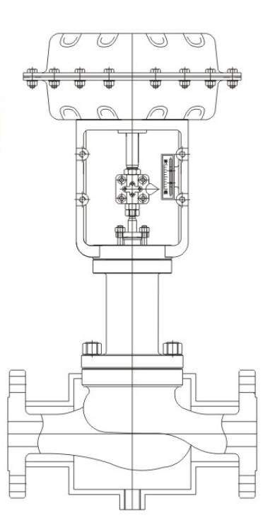
Outline Drawing
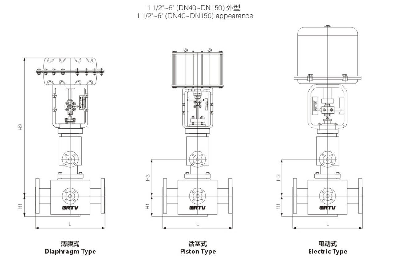
Appearance Dimension
Unit:mm
| DN (inch) | DN (mm) | ANSI150 PN16/25 GB/T12221 | ANSI150 PN16/25 GB/T17213.3 | ANSI300 PN40 GB/T17213.3 | ANSI600 PN64/100 | H1 | H2 | H3 | Pipe Diameter | Electrical Actuator | Pneumatic Actuator |
|---|
| 1 1/2 | 40 | 340 | 370 | 370 | 380 | 95 | 665 | 280 | 50 | 381LSB-30 | ZJHA/B 23 |
| 2 | 50 | 400 | 400 | 400 | 420 | 100 | 670 | 330 | 80 | 381LSB-30 | ZJHA/B 23 |
| 2 1/2 | 65 | 430 | 440 | 440 | 460 | 125 | 810 | 383 | 100 | 381LSB-50 | ZJHA/B 34 |
| 3 | 80 | 460 | 470 | 470 | 470 | 125 | 810 | 385 | 125 | 381LSB-50 | ZJHA/B 34 |
| 4 | 100 | 510 | 540 | 540 | 550 | 135 | 860 | 433 | 150 | 381LSB-50 | ZJHA/B 34 |
| 5 | 125 | 550 | 600 | 600 | 600 | 146 | 1100 | 605 | 200 | 381LSC-99 | ZJHA/B 45 |
| 6 | 150 | 600 | 660 | 660 | 660 | 170 | 1190 | 605 | 200 | 381LSC-99 | ZJHA/B 45 |
Manufacturing Process
Step 1: Order and Design
Confirm the customer’s requirements, including valve size, pressure rating, body material, jacket structure, trim material, and actuator type. According to the working conditions, engineers prepare drawings and technical specifications for the jacketed single seat control valve to ensure the design meets process temperature control and flow regulation needs.
Step 2: Forging & Casting
The main pressure-bearing parts such as valve body, bonnet, and jacket-related components are produced by forging or precision casting, depending on the material and structure requirements. For a jacketed single seat control valve, special attention is given to the casting quality of the jacket chamber to ensure strength, sealing performance, and uniform heat transfer.
Step 3: Machining
All raw parts are machined by CNC lathes, milling machines, and drilling equipment. Key dimensions such as flange faces, seat bore, stem hole, and jacket connection ports are precisely processed. During this stage, the jacketed single seat control valve body and internal trim parts must meet strict tolerance and surface finish requirements.
Step 4: Assembly
After machining inspection, workers assemble the valve body, seat, plug, stem, bonnet, gasket, and actuator step by step. For the jacketed single seat control valve, the jacket section, sealing surfaces, and control components are assembled carefully to ensure stable operation and reliable shut-off performance.
Step 5: Testing & Quality Assurance
Each valve undergoes pressure test, seat leakage test, air tightness test, stroke calibration, and functional inspection before delivery. For every jacketed single seat control valve, the jacket chamber is also checked for pressure resistance and sealing reliability to guarantee safe performance under operating conditions.
Step 6: Painting and Finishing
After passing all inspections, the valve surface is cleaned, polished, painted, and labeled according to order requirements. Final finishing includes nameplate installation, protective covering for flange faces, and packing preparation before shipment.
Applications
Control Valve suitable for use in situations requiring insulation.
These valves are widely used in:
Agriculture and Irrigation
Factory Environment
Why Choose Us
Superior Quality

Our valves are manufactured using premium materials and undergo rigorous quality testing to ensure reliable performance in demanding industrial applications.
Advanced Technology

Equipped with state-of-the-art CNC machining centers and precision manufacturing equipment, we deliver valves with exceptional accuracy and consistency.
Competitive Pricing

Through optimized manufacturing processes and bulk material procurement, we offer high-quality valves at competitive prices without compromising on quality.
Expert Support

Our experienced technical team provides comprehensive support from product selection to after-sales service, ensuring optimal valve performance for your specific application.