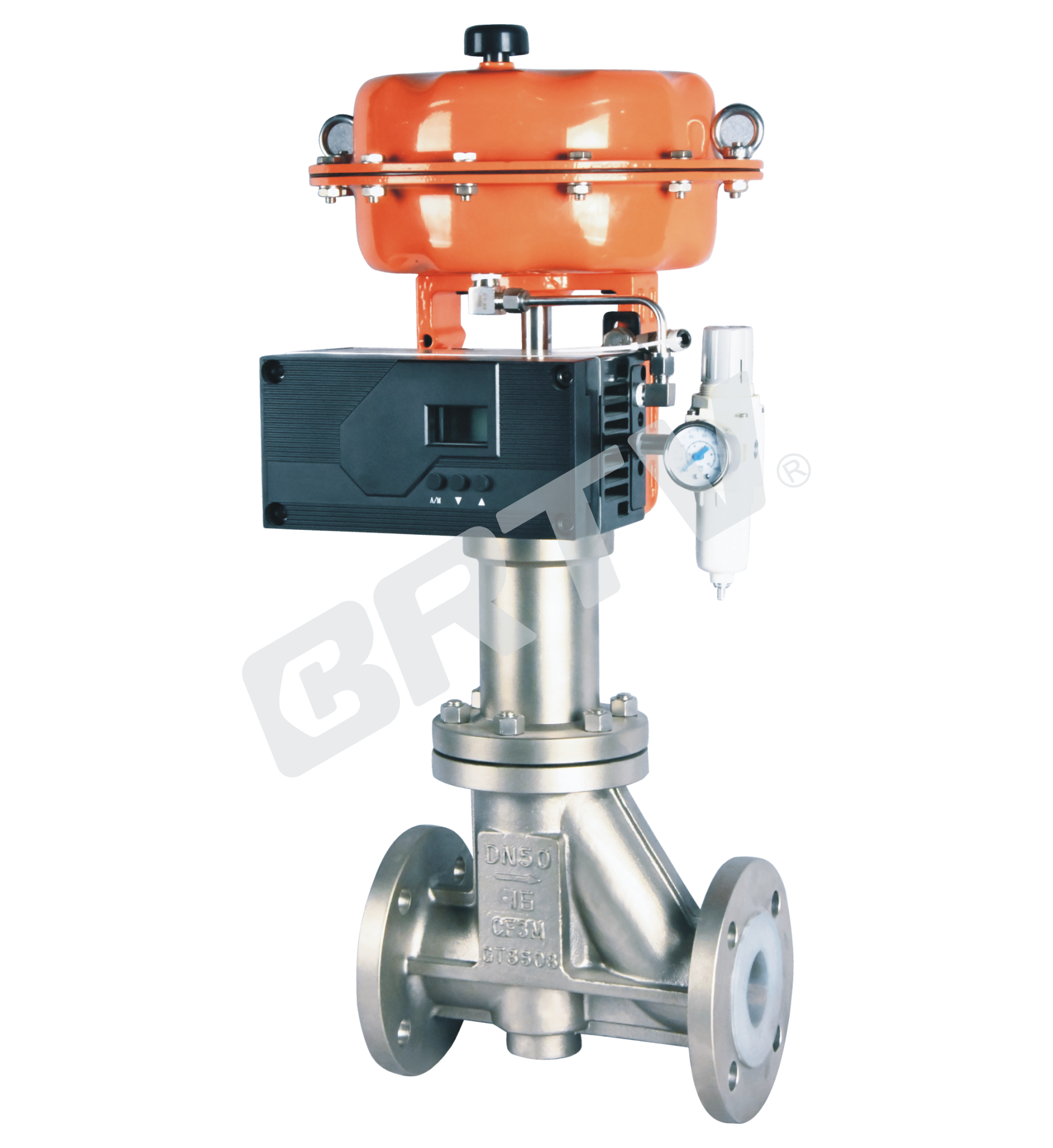
Fluorine Lined Control Valve
Fluorine Lined Control Valve is a kind of anti–corrosion straight through single seat control valve. The inner wall of the valve body and the components inside the valve are lined with F46 anti–corrosion materials. The PTFE inside the valve will be completely separated from the outside media.
It is used for corrosion of all chemical media, and has excellent sealing. It is equipped with multi–spring pneumatic diaphragm actuator or electric actuator. It has features: small volume, light weight, large output force, easy to install.
Standard Specifications
| Manner | Straight Through Single Seat Ball Valve |
|---|
| Nominal Diameter | 15, 20, 25, 40, 50, 65, 80, 100, 125, 150, 200 mm |
| Nominal Pressure | PN1.0, PN1.6, PN2.5 |
| Type of Connection | Flange Type: RF |
| Material of Body and Bonnet | The operating temperature & pressure range of various materials |
| Working Temperature | -20 ~ +120 °C (Lined F46); -20 ~ +150 °C (Lined PFA) |
| Gland Manner | Screw Fastening Type |
| Packing | V-Type PTFE Packing |
| Gasket | Plain Type, Zigzag Type / Stainless Steel (SUS304, SUS316, SUS316L) and other alloys |
| Surface Coating | Blue (Epoxy). When the valve body material is stainless steel, coating is not applied |
Cv Value and Stroke
| Nominal Diameter | Seat Diameter | Rated Cv | Rated Stroke |
|---|
| 15 | 3 | 0.09 | 10 |
| 15 | 4 | 0.14 | 10 |
| 15 | 5 | 0.23 | 10 |
| 15 | 6 | 0.37 | 10 |
| 15 | 7 | 0.60 | 10 |
| 15 | 8 | 0.95 | 10 |
| 20 | 10 | 1.4 | 10 |
| 20 | 12 | 2.4 | 10 |
| 20 | 15 | 3.7 | 10 |
| 20 | 20 | 5.9 | 10 |
| 25 | 12 | 2.4 | 10 |
| 25 | 15 | 3.7 | 10 |
| 25 | 20 | 5.9 | 10 |
| 25 | 25 | 9.4 | 10 |
| 32 | 20 | 5.9 | 10 |
| 32 | 25 | 9.4 | 10 |
| 32 | 32 | 14 | 10 |
| 40 | 25 | 9.4 | 25 |
| 40 | 32 | 14 | 25 |
| 40 | 40 | 23 | 25 |
| 50 | 32 | 14 | 25 |
| 50 | 40 | 23 | 25 |
| 50 | 50 | 37 | 25 |
| 65 | 40 | 23 | 25 |
| 65 | 50 | 37 | 25 |
| 65 | 65 | 59 | 25 |
| 80 | 50 | 37 | 40 |
| 80 | 65 | 59 | 40 |
| 80 | 80 | 82 | 40 |
| 100 | 65 | 59 | 40 |
| 100 | 80 | 82 | 40 |
| 100 | 100 | 117 | 40 |
| 150 | 100 | 117 | 60 |
| 150 | 125 | 195 | 60 |
| 150 | 150 | 280 | 60 |
| 200 | 125 | 250 | 60 |
| 200 | 150 | 400 | 60 |
| 200 | 200 | 630 | 60 |
Actuator
| Item | Pneumatic Diaphragm Type | Electronic Type | Intelligent Type |
|---|
| Model | ZJHA/B | 381L Series | ZM Series |
| Type | Multiple Springs Type | 381L Series | ZM Series |
| Service | Regulation | Regulation | Regulation |
| Supply Gas Pressure / Supply Voltage | Supply Gas Pressure (spring range): 140–100 kPa; 160–200 kPa; 280–400 kPa; 400–840 kPa | Voltage: 220/380V 50Hz; Input Signal: 4–20 mA DC; Voltage: 220/380V 50Hz; Input Signal: 4–20 mA DC | Voltage: 220/380V 50Hz; Input Signal: 4–20 mA DC; Voltage: 220/380V 50Hz; Input Signal: 4–20 mA DC |
| Connector | Air Piping: RC1/4 | Air Piping: G1/8, G1/4, G1/2, G3/8 | Wiring: PG13.5 |
| Positive Action | Adding Pressure, Valve Will Be Closed | Inputting the Signal, Valve Will Be Closed | Inputting the Signal, Valve Will Be Closed |
| Negative Action | Adding Pressure, Valve Will Be Opened | Inputting the Signal, Valve Will Be Opened | Inputting the Signal, Valve Will Be Opened |
| Hysteresis | ≤ 1% FS (with Positioner) | ≤ 1% FS | ≤ ±1% FS |
| Limit of Intrinsic Error | ≤ ±1% FS (with Positioner) | ≤ ±1% FS | ≤ ±1% FS |
| Ambient Temperature | Normal Temperature Type: −30 ~ +70°C; High Temperature Type: 0 ~ +100°C; Low Temperature Type: −40 ~ +40°C | −20 ~ +70°C | −25 ~ +70°C |
| Painting Color | Blue Scale 10B5/10 | — | — |
| Accessory | Positioner / Air Filtration Pressure Reducing Valve / Transmitter / Handwheel | Integrated Type | Integrated Type |
Model Selection Parameter Table
| Item | Parameter | DN20 | DN25 | DN32 | DN40 | DN50 | DN65 | DN80 | DN100 | DN125 | DN150 | DN200 |
|---|
| Rated Flow Cv Value | Equal Percentage | - | 8 | 12 | 20 | 32 | 50 | 70 | 100 | 200 | 240 | 630 |
| Rated Flow Cv Value | Straight | 5 | 10 | 16 | 25 | 38 | 63 | 80 | 120 | 220 | 300 | 690 |
| Stroke | | 16 | 16 | 16 | 25 | 25 | 25 | 40 | 40 | 40 | 60 | 60 |
| Pneumatic Actuator Model | | ZHA/B-22 | ZHA/B-22 | ZHA/B-22 | ZHA/B-23 | ZHA/B-23 | ZHA/B-23 | ZHA/B-34 | ZHA/B-34 | ZHA/B-34 | ZHA/B-45 | ZHA/B-45 |
| Active Area Ae (cm²) | | 350 | 350 | 350 | 350 | 350 | 350 | 560 | 560 | 560 | 900 | 900 |
| Open | Spring Range 20–100 kPa | 1.16 | 0.70 | 0.44 | 0.28 | 0.18 | 0.17 | 0.11 | 0.07 | 0.07 | 0.05 | 0.03 |
| Open | Spring Range 40–200 kPa | 3.34 | 2.14 | 1.31 | 0.84 | 0.53 | 0.51 | 0.33 | 0.21 | 0.22 | 0.15 | 0.09 |
| Open | Spring Range 80–240 kPa | 6.40 | 4.99 | 3.05 | 1.95 | 1.25 | 1.18 | 0.78 | 0.50 | 0.51 | 0.36 | 0.21 |
| Close | Spring Range 20–100 kPa | 2.23 | 2.14 | 0.87 | 0.56 | 0.35 | 0.34 | 0.22 | 0.14 | 0.15 | 0.10 | 0.06 |
| Close | Spring Range 40–200 kPa | 6.40 | 6.40 | 5.86 | 3.64 | 2.30 | 2.21 | 1.43 | 0.91 | 0.95 | 0.66 | 0.37 |
| Close | Spring Range 80–240 kPa | 6.40 | 6.40 | 6.40 | 5.04 | 3.18 | 3.06 | 1.98 | 1.26 | 1.32 | 0.92 | 0.52 |
The Material of Valve And Components, Range of Using Temperature · Allowable Leakage of Seat
| Component | Item | Lined F46 | Lined PFA/F4/F46 |
|---|
| Body | Material | SCHP2 / A216-WCB, SCS13A / A351-CF8, SCS14A / A351-CF8M | SCHP2 / A216-WCB, SCS13A / A351-CF8, SCS14A / A351-CF8M |
| Body | Treatment | Lined F46 | Lined PFA / F4 / F46 |
| Core | Material | PO / PE / FRPP / SUS420 / SUS304 / SUS316 / SUS316L | PO / PE / FRPP / SUS420 / SUS304 / SUS316 / SUS316L |
| Core | Treatment | Lined F4 / F46 / PFA / PO / PE / FRPP | Lined F4 / F46 / PFA / PO / PE / FRPP |
| Bellows (Aim at bellows type) | Material | SUS420 / SUS304 / SUS316 / SUS316L | SUS420 / SUS304 / SUS316 / SUS316L |
| Allowable Leakage of Seat | ANSI | Class IV | Class IV |
| Operating Temperature (°C) | | -20 ~ +120 | -20 ~ +150 |
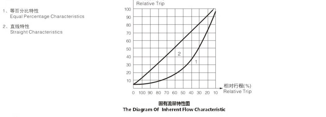
Typical Flow Characteristic of Valve
The Size of Control Valve and Hole Shrinkage Internals & Trim; Rated Cv.
| Valve Size (inch/mm) | Core Size (inch/mm) | Rated Stroke (mm) | Characteristic | 10% | 25% | 50% | 75% | 100% |
|---|
| 3/4 (20) | 1/4 (8) | 16 | Equal Percentage | 0.09 | 0.17 | 0.34 | 0.95 | 1.87 |
| 3/4 (20) | 1/4 (8) | 16 | Straight | 0.27 | 0.68 | 1.09 | 1.49 | 2.10 |
| 3/4 (20) | 3/8 (10) | 16 | Equal Percentage | 0.14 | 0.27 | 0.53 | 1.48 | 2.92 |
| 3/4 (20) | 3/8 (10) | 16 | Straight | 0.42 | 1.06 | 1.69 | 2.32 | 3.27 |
| 3/4 (20) | 1/2 (15) | 16 | Equal Percentage | 0.22 | 0.43 | 0.85 | 2.37 | 4.67 |
| 3/4 (20) | 1/2 (15) | 16 | Straight | 0.67 | 1.66 | 2.65 | 3.65 | 5.13 |
| 3/4 (20) | 3/4 (20) | 16 | Equal Percentage | 0.34 | 0.68 | 1.35 | 3.74 | 7.35 |
| 3/4 (20) | 3/4 (20) | 16 | Straight | 1.05 | 2.60 | 4.16 | 5.72 | 8.05 |
| 1 (25) | 1/2 (15) | 16 | Equal Percentage | 0.22 | 0.43 | 0.85 | 2.37 | 4.67 |
| 1 (25) | 1/2 (15) | 16 | Straight | 0.67 | 1.66 | 2.56 | 3.65 | 5.13 |
| 1 (25) | 3/4 (20) | 16 | Equal Percentage | 0.34 | 0.68 | 1.35 | 3.74 | 7.35 |
| 1 (25) | 3/4 (20) | 16 | Straight | 1.05 | 2.60 | 4.16 | 5.72 | 8.05 |
| 1 (25) | 1 (25) | 16 | Equal Percentage | 0.55 | 1.08 | 2.14 | 5.93 | 11.67 |
| 1 (25) | 1 (25) | 16 | Straight | 1.67 | 4.15 | 6.64 | 9.11 | 12.84 |
| 1 1/4 (32) | 3/4 (20) | 25 | Equal Percentage | 0.34 | 0.68 | 1.35 | 3.74 | 7.35 |
| 1 1/4 (32) | 3/4 (20) | 25 | Straight | 1.05 | 2.60 | 4.16 | 5.72 | 8.05 |
| 1 1/4 (32) | 1 (25) | 25 | Equal Percentage | 0.55 | 1.08 | 2.14 | 5.93 | 11.67 |
| 1 1/4 (32) | 1 (25) | 25 | Straight | 1.67 | 4.15 | 6.64 | 9.11 | 12.84 |
| 1 1/4 (32) | 1 1/4 (32) | 25 | Equal Percentage | 0.87 | 1.73 | 3.42 | 9.49 | 18.67 |
| 1 1/4 (32) | 1 1/4 (32) | 25 | Straight | 2.67 | 6.63 | 10.62 | 14.58 | 20.54 |
| 1 1/2 (40) | 1 (25) | 25 | Equal Percentage | 0.55 | 1.08 | 2.14 | 5.93 | 11.67 |
| 1 1/2 (40) | 1 (25) | 25 | Straight | 1.67 | 4.15 | 6.64 | 9.11 | 12.84 |
| 1 1/2 (40) | 1 1/4 (32) | 25 | Equal Percentage | 0.87 | 1.73 | 3.42 | 9.49 | 18.67 |
| 1 1/2 (40) | 1 1/4 (32) | 25 | Straight | 2.67 | 6.63 | 10.62 | 14.58 | 20.54 |
| 1 1/2 (40) | 1 1/2 (40) | 25 | Equal Percentage | 1.36 | 2.72 | 5.35 | 14.82 | 29.17 |
| 1 1/2 (40) | 1 1/2 (40) | 25 | Straight | 4.17 | 10.37 | 16.59 | 22.79 | 32.09 |
Outline Drawing and Weight
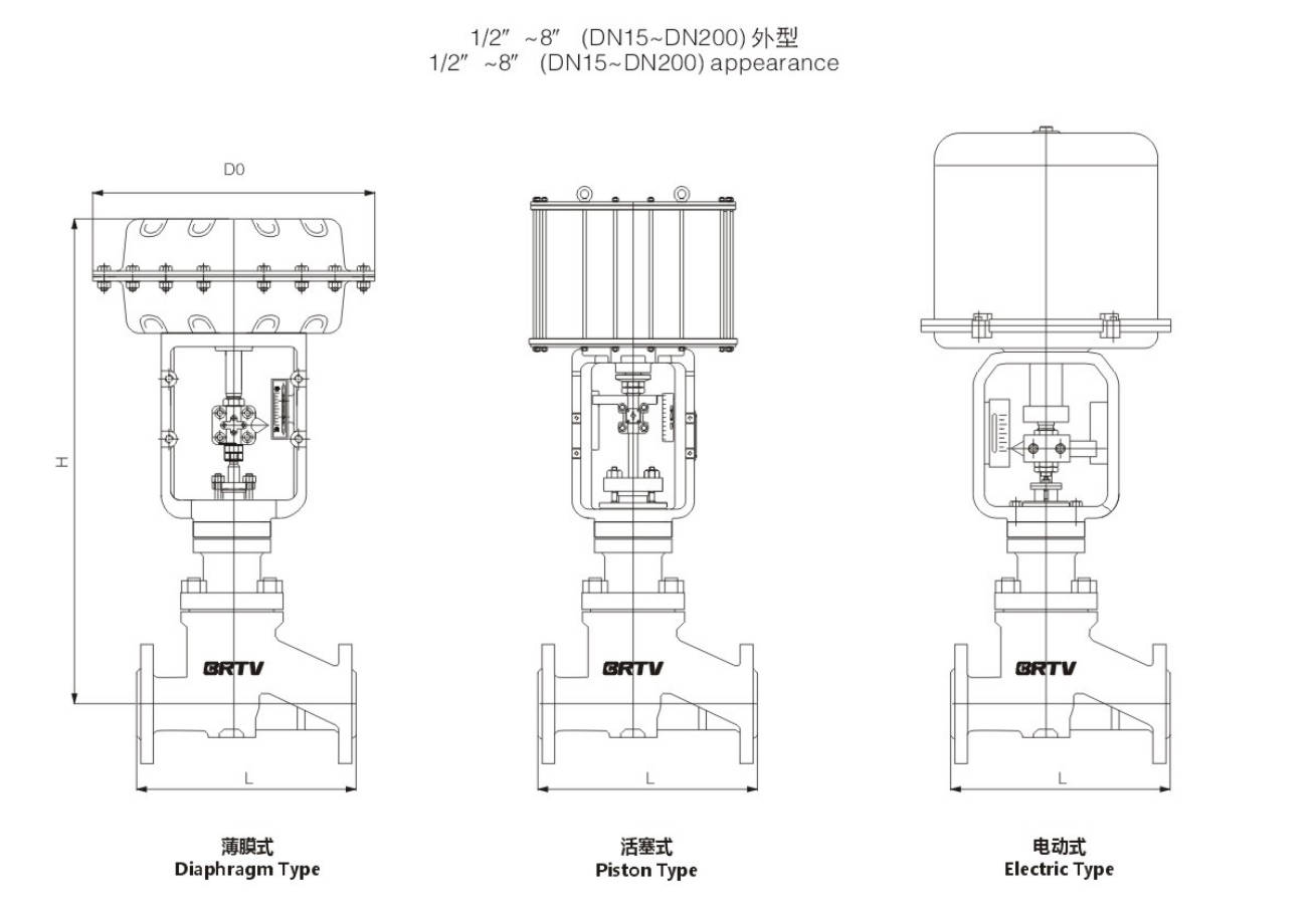
Unit:mm
| NPS | DN | D0 | L | H |
|---|
| 1/2" | DN15 | 285 | 130 | 487 |
| 3/4" | DN20 | 285 | 150 | 487 |
| 1" | DN25 | 285 | 160 | 493 |
| 1 1/4" | DN32 | 285 | 180 | 524 |
| 1 1/2" | DN40 | 285 | 200 | 530 |
| 2" | DN50 | 285 | 230 | 538 |
| 2 1/2" | DN65 | 360 | 290 | 686 |
| 3" | DN80 | 360 | 310 | 706 |
| 4" | DN100 | 360 | 350 | 726 |
| 5" | DN125 | 470 | 400 | 969 |
| 6" | DN150 | 470 | 480 | 969 |
| 8" | DN200 | 470 | 600 | 1009 |
Manufacturing Process
Step 1: Order and Design
Confirm the working conditions, including medium, temperature, pressure, flow rate, and corrosion level. Based on the project requirements, select the proper body material, lining material, actuator type, and trim structure for the fluorine lined control valve. Then prepare drawings and production documents.
Step 2: Forging & Casting
The valve body, bonnet, and other pressure-bearing parts are produced by casting or forging according to the design. Raw materials must meet the required standards for strength and corrosion resistance. Special attention is given to the inner cavity structure to ensure it is suitable for fluorine lining in the fluorine lined control valve.
Step 3: Machining
All key components are machined, including the valve body, bonnet, flange faces, seat area, stem hole, and connection parts. Machining accuracy and surface finish are strictly controlled to guarantee proper fitting and sealing performance of the fluorine lined control valve.
Step 4: Assembly
After machining and inspection, the valve parts are assembled step by step. This includes installation of the fluorine-lined body components, trim parts, stem, actuator, and accessories. During assembly of the fluorine lined control valve, cleanliness and alignment are very important to avoid damage to the lining.
Step 5: Testing & Quality Assurance
Each fluorine lined control valve must undergo pressure testing, sealing testing, action testing, and visual inspection. If required, lining integrity and thickness are also checked to ensure the valve performs safely and reliably under corrosive service conditions.
Step 6: Painting and Finishing
After final inspection, the external surface is cleaned, painted, and marked. Nameplate, inspection tag, and packaging are completed according to order requirements, so the finished fluorine lined control valve is ready for delivery.
Applications
In practical applications, the advantages of pneumatic fluorine lined control valves lie in their high corrosion resistance and good stability, which enable them to adapt to various industrial production processes in complex environments. Additionally, pneumatic fluorine lined control valves also have strong adjustability and reliability, capable of meeting the requirements of different control systems. When selecting and applying pneumatic fluorine-lined control valves, it is necessary to fully consider actual needs and working conditions to choose the appropriate model and specification, and ensure their safe and stable operation in the production process.
These valves are widely used in:
Agriculture and Irrigation
Factory Environment
Why Choose Us
Superior Quality

Our valves are manufactured using premium materials and undergo rigorous quality testing to ensure reliable performance in demanding industrial applications.
Advanced Technology

Equipped with state-of-the-art CNC machining centers and precision manufacturing equipment, we deliver valves with exceptional accuracy and consistency.
Competitive Pricing

Through optimized manufacturing processes and bulk material procurement, we offer high-quality valves at competitive prices without compromising on quality.
Expert Support

Our experienced technical team provides comprehensive support from product selection to after-sales service, ensuring optimal valve performance for your specific application.