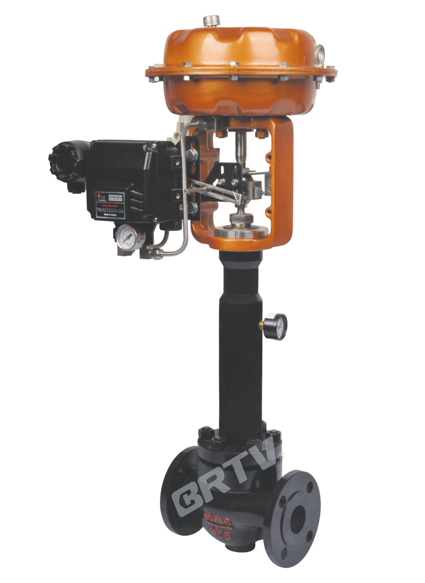
Bellows Cage Type Control Valve
bellows cage type control valve is a kind of control valve with pressure balanced. The valve body structure is compact, the fluid channel is S–streamline. It has advantages of small pressure rise loss, large flow, and wide adjustable range.
The upper bonnet adopts bellows sealing structure, which can completely eliminate the possibility of leakage of process media from the movement gap of the stem. And it is one of the remarkable characteristics of bellows sealing valve. Due to the variability and prominence of the bellows element itself with the anti–aging property, this kind of control valve completely overcomes the weakness of packing sealing valve, such as packing aging and temperature difference sensitivity. Secondly, using the bellows – packing double seal structure, it has better safety and reliability. Therefore, it is widely used in the automatic control system of highly toxic, highly corrosive, radioactive and other rare and special media.
The valve core has large guiding area and good vibration resistance. The control valve is equipped with multi–spring diaphragm actuator or electric actuator, and has compact structure, large output torque.
Standard Specification
| Manner | Straight Through Single Seat Cast Ball Valve |
|---|
| Nominal Diameter | 40, 50, 65, 80, 100, 125, 150, 200 mm |
| Nominal Pressure | ANSI Class 125, 150, 300; JIS 10K, 16K, 20K, 40K; PN 1.6, 4.0 MPa |
| Type of Connection | Flange Type: FF, RF, RJ, TG, MFM / Weld Type: SW (4050 mm), BW (65200 mm) |
| The Material of Body and Bonnet | SCPH2/WCB, SCPH21/WC6, SCS13A/CF8, SCS14A/CF8M, SCS16A/CF3M. Titanium and other alloy materials can be used depending on operating temperature and pressure range. |
| Bonnet Manner | Bellow Seal Type: -196 ~ +350 °C |
| Gland Manner | Screw Fastening Type |
| Packing | V-type PTFE Packing, Graphite Packing |
| Gasket | Plain type, Zigzag type / Stainless steel (SUS304, SUS316, SUS316L) and other alloys |
| Surface Coating | Blue (Epoxy). When the valve body material is stainless steel, coating is not applied. |
Flange Standard: JIS B2201-1984, JB/T79.1-94 (PN1.6MPA), JB/T79.2-94 (PN4.0, 6.4MPA), ANSI B16.5-2009, HG20592-2009, HG20615-2009
High Precision Core Cv Value (%VF, LVF)
| Nominal Diameter | Seat Diameter | Rated Cv | Equal Percentage Characteristics (Metal Seat) | Rated Stroke (mm) |
|---|
| 32 | 25 | 11 | △ | 25 |
| 32 | 32 | 17 | △ | 25 |
| 40 | 25 | 11 | △ | 25 |
| 40 | 32 | 17 | △ | 25 |
| 40 | 40 | 24 | △ | 25 |
| 50 | 32 | 17 | △ | 25 |
| 50 | 40 | 24 | △ | 25 |
| 50 | 50 | 44 | △ | 25 |
| 65 | 40 | 24 | △ | 40 |
| 65 | 50 | 44 | △ | 40 |
| 65 | 65 | 68 | △ | 40 |
| 80 | 50 | 44 | △ | 40 |
| 80 | 65 | 68 | △ | 40 |
| 80 | 80 | 99 | △ | 40 |
| 100 | 65 | 68 | △ | 40 |
| 100 | 80 | 99 | △ | 40 |
| 100 | 100 | 175 | △ | 40 |
| 150 | 100 | 175 | △ | 60 |
| 150 | 125 | 275 | △ | 60 |
| 150 | 150 | 360 | △ | 60 |
| 200 | 125 | 275 | △ | 60 |
| 200 | 150 | 360 | △ | 60 |
| 200 | 200 | 650 | △ | 60 |
Note: Symbol △ Means The Range of Valve Specifications.
Actuator
| Item | Pneumatic Diaphragm Type | Electronic Type | Intelligent Type |
|---|
| Model | ZJHA/B | 381 Series | ZM Series |
| Type | Multiple Springs Type | | |
| Service | Regulation | Regulation | Regulation |
| Supply Gas Pressure / Supply Voltage | Supply Gas Pressure (spring range): 280 (80–240) kPa; 400 (80–240) kPa | Voltage: 220 / 380V 50Hz; Input Signal: 4–20 mA DC | Voltage: 220 / 380V 50Hz; Input Signal: 4–20 mA DC |
| Connector | Air Piping: RC1/4 | Air Piping: G1/8, G1/4, G1/2, G3/8 | Wiring: PG13.5 |
| Positive Action | Adding Pressure — Valve Will Be Closed | Inputting the Signal — Valve Will Be Closed | Inputting the Signal — Valve Will Be Closed |
| Negative Action | Adding Pressure — Valve Will Be Opened | Inputting the Signal — Valve Will Be Opened | Inputting the Signal — Valve Will Be Opened |
| Hysteresis | ≤1% FS (with Positioner); ≤5% FS (no Positioner) | ≤ ±1% FS | ≤ ±1% FS |
| Limit of Intrinsic Error | ≤1% FS (with Positioner); ≤11% FS (no Positioner) | ≤ ±1% FS | ≤ ±1% FS |
| Ambient Temperature | Normal Temperature Type: −30 ~ +70°C; High Temperature Type: 0 ~ +100°C; Low Temperature Type: −40 ~ +100°C | −20 ~ +70°C | −25 ~ +70°C |
| Painting Color | Blue Scale 1085/10 | | |
| Accessory | Positioner; Air Filtration Pressure Reducing Valve; Transmitter; Handwheel | Integrated Type | Integrated Type |
Model Selection Parameter Table
| Section | Item | 10 | 12 | 15 | 20 | 25 | 32 | 40 | 50 | 65 | 80 | 100 | 125 | 150 | 200 |
|---|
| Seat Diameter (mm) | Equal Percentage Cv | 1.6 | 2.5 | 4 | 6.3 | 10 | 16 | 25 | 40 | 63 | 100 | 160 | 250 | 400 | 630 |
| Seat Diameter (mm) | Straight Cv | 1.8 | 2.8 | 4.4 | 6.9 | 11 | 17.6 | 27.5 | 44 | 69 | 110 | 176 | 275 | 440 | 690 |
| Nominal Diameter | Stroke | Optional Flow Coefficient Cv | | | | | | | | | | | | | |
| DN25 | 16 mm | ● | ● | ● | ★ | | | | | | | | | | |
| DN32 | 16 mm | ● | ● | ● | ● | ★ | | | | | | | | | |
| DN40 | 25 mm | ○ | ○ | ○ | ○ | ○ | ★ | | | | | | | | |
| DN50 | 25 mm | | ○ | ○ | ○ | ○ | ● | ★ | | | | | | | |
| DN65 | 25 mm | | | ○ | ○ | ○ | ● | ● | ★ | | | | | | |
| DN80 | 40 mm | | | | | | ○ | ○ | ○ | ★ | | | | | |
| DN100 | 40 mm | | | | | | ○ | ○ | ○ | ● | ★ | | | | |
| DN125 | 40 mm | | | | | | | | ○ | ○ | ○ | ★ | | | |
| DN150 | 60 mm | | | | | | | | | ○ | ○ | ● | ★ | | |
| DN200 | 60 mm | | | | | | | | | | ○ | ○ | ● | ● | ★ |
| Pneumatic Actuator Diaphragm Active Area Ae (cm²) | Model | | | | | | | | | | | | | | |
| ZJHA/B-22 | 350 | | | | | | | | | | | | | |
| ZJHA/B-23 | 350 | | | | | | | | | | | | | |
| ZJHA/B-34 | 560 | | | | | | | | | | | | | |
| ZJHA/B-45 | 900 | | | | | | | | | | | | | |
| Action | Range of Spring | 10 | 12 | 15 | 20 | 25 | 32 | 40 | 50 | 65 | 80 | 100 | 125 | 150 | 200 |
| Open | 20–100 kPa | 4.46 | 3.09 | 1.98 | 1.16 | 0.7 | 0.44 | 0.28 | 0.18 | 0.17 | 0.11 | 0.07 | 0.07 | 0.05 | 0.03 |
| Open | 40–200 kPa | 6.4 | 6.4 | 5.94 | 3.34 | 2.14 | 1.31 | 0.84 | 0.53 | 0.51 | 0.33 | 0.21 | 0.22 | 0.15 | 0.09 |
| Open | 80–240 kPa | 6.4 | 6.4 | 6.4 | 6.4 | 4.99 | 3.05 | 1.95 | 1.25 | 1.18 | 0.78 | 0.5 | 0.51 | 0.36 | 0.21 |
| Close | 20–100 kPa | 6.4 | 6.19 | 3.96 | 2.23 | 2.14 | 0.87 | 0.56 | 0.35 | 0.34 | 0.22 | 0.14 | 0.15 | 0.1 | 0.06 |
| Close | 40–200 kPa | 6.4 | 6.4 | 6.4 | 6.4 | 6.4 | 5.86 | 3.64 | 2.3 | 2.21 | 1.43 | 0.91 | 0.95 | 0.66 | 0.37 |
| Close | 80–240 kPa | 6.4 | 6.4 | 6.4 | 6.4 | 6.4 | 6.4 | 5.04 | 3.18 | 3.06 | 1.98 | 1.26 | 1.32 | 0.92 | 0.52 |
Typical Flow Characteristic of Valve
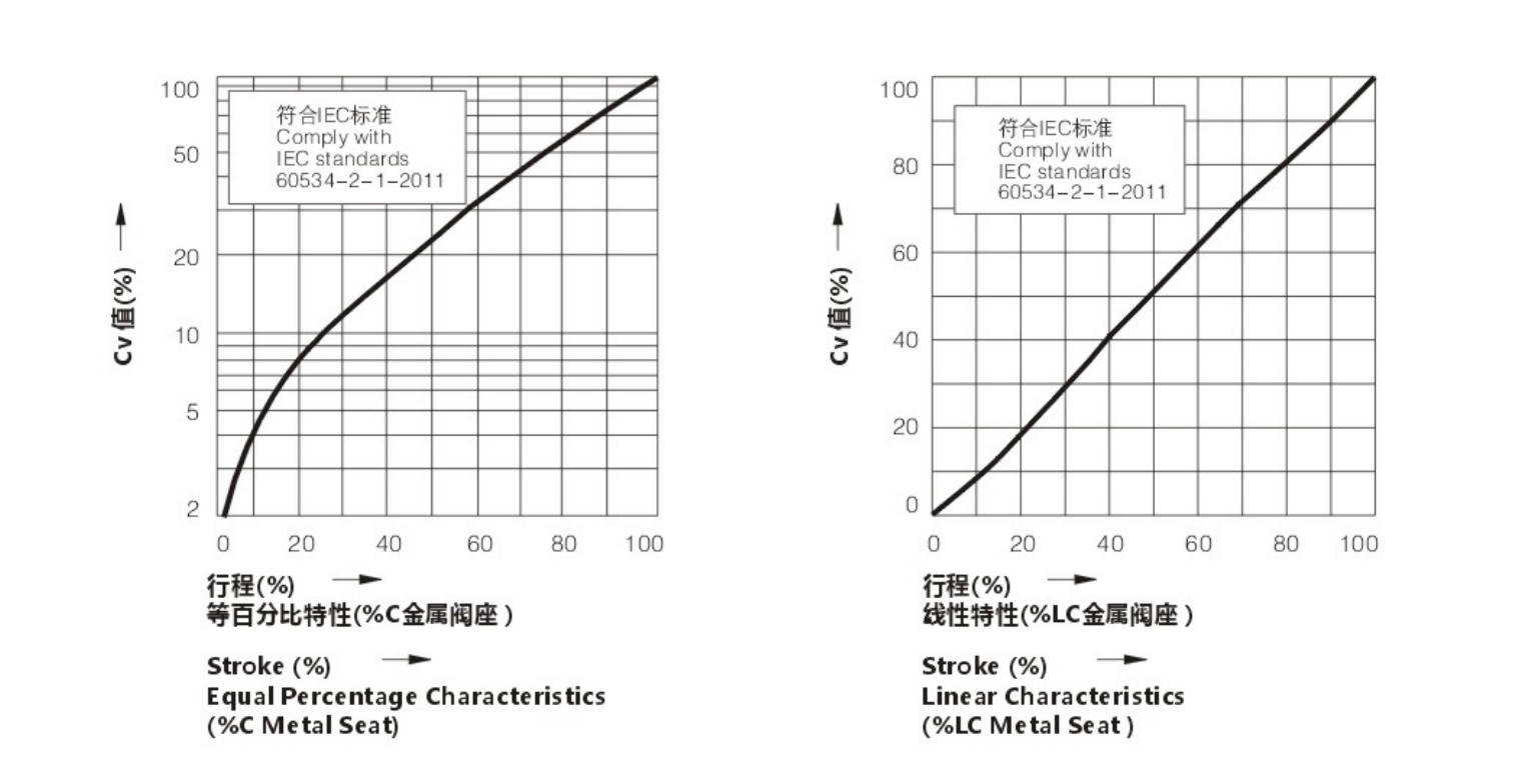
The Size of Control Valve and Hole Shrinkage Internals & Trim; Rated Cv.
| Valve Size inch (mm) | Rated Stroke (mm) | Cv Type | 10% | 30% | 50% | 70% | 100% | 10% | 30% | 50% | 70% | 100% |
|---|
| | | Equal % | Equal % | Equal % | Equal % | Equal % | Straight | Straight | Straight | Straight | Straight |
| 3/4 (20) | 16 | Cv1 | 0.09 | 0.17 | 0.34 | 0.95 | 1.6 | 0.27 | 0.68 | 1.09 | 1.49 | 1.8 |
| 3/4 (20) | 16 | Cv2 | 0.14 | 0.27 | 0.53 | 1.48 | 2.5 | 0.42 | 1.06 | 1.69 | 2.32 | 2.8 |
| 3/4 (20) | 16 | Cv3 | 0.22 | 0.43 | 0.85 | 2.37 | 4 | 0.67 | 1.66 | 2.65 | 3.65 | 4.4 |
| 1 (25) | 16 | Cv1 | 0.22 | 0.43 | 0.85 | 2.37 | 4 | 0.67 | 1.66 | 2.65 | 3.65 | 4.4 |
| 1 (25) | 16 | Cv2 | 0.34 | 0.68 | 1.35 | 3.74 | 6.3 | 1.05 | 2.60 | 4.16 | 5.72 | 6.9 |
| 1 1/4 (32) | 25 | Cv1 | 0.34 | 0.68 | 1.35 | 3.74 | 6.3 | 1.05 | 2.60 | 4.16 | 5.72 | 6.9 |
| 1 1/4 (32) | 25 | Cv2 | 0.55 | 1.08 | 2.14 | 5.93 | 10 | 1.67 | 4.15 | 6.64 | 9.11 | 11 |
| 1 1/2 (40) | 25 | Cv1 | 0.55 | 1.08 | 2.14 | 5.93 | 10 | 1.67 | 4.15 | 6.64 | 9.11 | 11 |
| 1 1/2 (40) | 25 | Cv2 | 0.87 | 1.73 | 3.42 | 9.49 | 16 | 2.67 | 6.63 | 10.62 | 14.58 | 17.6 |
| 2 (50) | 25 | Cv1 | 0.87 | 1.73 | 3.42 | 9.49 | 16 | 2.67 | 6.63 | 10.62 | 14.58 | 17.6 |
| 2 (50) | 25 | Cv2 | 1.36 | 2.72 | 5.35 | 14.82 | 25 | 4.17 | 10.37 | 16.59 | 22.79 | 27.5 |
| 2 1/2 (65) | 40 | Cv1 | 1.36 | 2.72 | 5.35 | 14.82 | 25 | 4.17 | 10.37 | 16.59 | 22.79 | 27.5 |
| 2 1/2 (65) | 40 | Cv2 | 2.18 | 4.32 | 8.54 | 23.71 | 40 | 6.67 | 16.58 | 26.56 | 36.46 | 44 |
| 3 (80) | 40 | Cv1 | 2.18 | 4.32 | 8.54 | 23.71 | 40 | 6.67 | 16.58 | 26.56 | 36.46 | 44 |
| 3 (80) | 40 | Cv2 | 3.34 | 6.81 | 13.45 | 37.35 | 63 | 10.47 | 26.01 | 41.63 | 57.17 | 69 |
| 4 (100) | 40 | Cv1 | 3.34 | 6.81 | 13.45 | 37.35 | 63 | 10.47 | 26.01 | 41.63 | 57.17 | 69 |
| 4 (100) | 40 | Cv2 | 5.45 | 10.81 | 21.36 | 59.28 | 100 | 16.69 | 41.46 | 66.37 | 91.14 | 110 |
| 5 (125) | 60 | Cv1 | 13.62 | 10.81 | 21.36 | 59.28 | 100 | 16.69 | 41.46 | 66.37 | 91.14 | 110 |
| 5 (125) | 60 | Cv2 | 21.80 | 17.29 | 34.17 | 94.85 | 160 | 26.70 | 66.34 | 106.2 | 145.8 | 176 |
| 6 (150) | 60 | Cv1 | 21.80 | 17.29 | 34.17 | 94.85 | 160 | 26.70 | 66.34 | 106.2 | 145.8 | 176 |
| 6 (150) | 60 | Cv2 | 13.62 | 27.06 | 53.40 | 148.2 | 250 | 41.72 | 103.7 | 165.9 | 227.9 | 275 |
| 6 (150) | 60 | Cv3 | 21.80 | 43.23 | 85.42 | 237.1 | 400 | 66.75 | 165.85 | 265.5 | 364.6 | 440 |
| 8 (200) | 60 | Cv1 | 13.62 | 27.06 | 53.40 | 148.2 | 250 | 71.72 | 103.7 | 165.9 | 227.9 | 275 |
| 8 (200) | 60 | Cv2 | 21.80 | 43.23 | 85.42 | 237.1 | 400 | 66.75 | 165.85 | 265.5 | 364.6 | 440 |
The Material of Valve and Components, Range of Using Temperature · Allowable Leakage of Seat
Body Material: Carbon Steel
| Body Material | | SCPH2 / A216-WCB, SCPH21 / A217-WC6, SCPL1 / A352-LCB |
|---|
| Sleeve | Material | SUS630 |
| Sleeve | Treatment | HT |
| Core | Material | SUS410 |
| Core | Treatment | HT |
| Gasket | Material | SUS316L |
| Bellow | Material | SUS304 |
| Allowable Leakage of Seat | ANSI | Class III |
| Allowable Leakage of Seat | Rated CvX | 0.01% |
| Operating Temperature | SCPH2 / WCB Body | −17 ~ +350 °C |
| Operating Temperature | SCPH21 / WC6 Body | −17 ~ +350 °C |
| Operating Temperature | SCPL1 / LCB Body | −45 ~ +350 °C |
Body Material: Stainless Steel
| Body Material | | SCS13A / A351-CF8, SCS14A / A351-CF8M, SCS16A / A351-CF3M |
|---|
| Sleeve | Material | SUS304 / 316 / 316L |
| Sleeve | Treatment | ST |
| Core | Material | SUS304 / 316 / 316L |
| Core | Treatment | ST |
| Gasket | Material | SUS316L |
| Bellow | Material | SUS304 / 316 / 316L |
| Allowable Leakage of Seat | ANSI | Class III |
| Allowable Leakage of Seat | Rated CvX | 0.01% |
| Operating Temperature | | −196 ~ +350 °C |
Multi-spring Diaphragm Actuator
| Actuator Model | Air Pressure (kPa) | Spring Range (kPa) | 3/4 (20) | 1 (25) | 1 1/4 (32) | 1 1/2 (40) | 2 (50) | 2 1/2 (65) | 3 (80) | 4 (100) | 5 (125) | 6 (150) | 8 (200) |
|---|
| ZJHA/B-22 | 140 | 20–100 | 1.17 | 0.75 | – | – | – | – | – | – | – | – | – |
| ZJHA/B-22 | 240 | 40–200 | 2.73 | 1.75 | – | – | – | – | – | – | – | – | – |
| ZJHA/B-22 | 300 | 80–240 | 5.85 | 3.75 | – | – | – | – | – | – | – | – | – |
| ZJHA/B-23 | 140 | 20–100 | 1.64 | 1.05 | 0.63 | 0.40 | 0.26 | – | – | – | – | – | – |
| ZJHA/B-23 | 240 | 40–200 | 3.82 | 2.45 | 1.49 | 0.96 | 0.61 | – | – | – | – | – | – |
| ZJHA/B-23 | 300 | 80–240 | 8.19 | 5.24 | 3.19 | 2.05 | 1.31 | – | – | – | – | – | – |
| ZJHA/B-34 | 140 | 20–100 | – | – | 1.02 | 0.66 | 0.42 | 0.24 | 0.16 | 0.10 | – | – | – |
| ZJHA/B-34 | 240 | 40–200 | – | – | 2.38 | 1.53 | 0.98 | 0.58 | 0.38 | 0.24 | – | – | – |
| ZJHA/B-34 | 300 | 80–240 | – | – | 5.12 | 3.28 | 2.10 | 1.24 | 0.82 | 0.52 | – | – | – |
| ZJHA/B-45 | 140 | 20–100 | – | – | – | – | – | 0.40 | 0.26 | 0.17 | 0.11 | 0.07 | 0.02 |
| ZJHA/B-45 | 240 | 40–200 | – | – | – | – | – | 0.93 | 0.61 | 0.39 | 0.25 | 0.17 | 0.07 |
| ZJHA/B-45 | 300 | 80–240 | – | – | – | – | – | 1.98 | 1.32 | 0.84 | 0.54 | 0.37 | 0.16 |
381L Series of Electronic Actuator
| Model | Voltage Rating | 3/4 (20) | 1 (25) | 1 1/4 (32) | 1 1/2 (40) | 2 (50) | 2 1/2 (65) | 3 (80) | 4 (100) | 5 (125) | 6 (150) | 8 (200) |
|---|
| 381LSA-08 | 110V / 220V / 380V | 2.38 | 1.52 | 0.93 | 0.59 | 0.38 | – | – | – | – | – | – |
| 381LSA-08 | 110V / 220V / 380V | 1.91 | 1.22 | 0.74 | 0.47 | 0.30 | – | – | – | – | – | – |
| 381LSA-20 | 110V / 220V / 380V | 4.77 | 3.05 | 1.86 | 1.19 | 0.76 | 0.45 | – | – | – | – | – |
| 381LSA-20 | 110V / 220V / 380V | 3.82 | 2.44 | 1.49 | 0.95 | 0.61 | 0.36 | – | – | – | – | – |
| 381LSB-30 | 110V / 220V / 380V | – | – | 2.79 | 1.79 | 1.14 | 0.67 | 1.21 | 0.28 | 0.18 | 0.12 | 0.03 |
| 381LSB-30 | 110V / 220V / 380V | – | – | 2.23 | 1.43 | 0.91 | 0.54 | 0.96 | 0.22 | 0.14 | 0.10 | 0.02 |
| 381LSB-50 | 110V / 220V / 380V | – | – | 4.66 | 2.98 | 1.91 | 1.13 | 1.51 | 0.47 | 0.30 | 0.21 | 0.08 |
| 381LSB-50 | 110V / 220V / 380V | – | – | 3.73 | 2.38 | 1.52 | 0.90 | 1.20 | 0.38 | 0.24 | 0.16 | 0.06 |
| 381LSC-65 | 110V / 220V / 380V | – | – | – | – | – | 1.35 | 2.34 | 0.57 | 0.36 | 0.25 | 0.11 |
| 381LSC-65 | 110V / 220V / 380V | – | – | – | – | – | 1.08 | 1.87 | 0.45 | 0.29 | 0.20 | 0.08 |
| 381LSC-99 | 110V / 220V / 380V | – | – | – | – | – | 2.26 | 2.92 | 0.95 | 0.61 | 0.42 | 0.20 |
| 381LSC-99 | 110V / 220V / 380V | – | – | – | – | – | 1.80 | 2.33 | 0.76 | 0.48 | 0.33 | 0.15 |
| 381LSC-160 | 110V / 220V / 380V | – | – | – | – | – | – | – | – | 0.97 | 0.67 | 0.35 |
| 381LSC-160 | 110V / 220V / 380V | – | – | – | – | – | – | – | – | 0.78 | 0.54 | 0.27 |
Outline Drawing
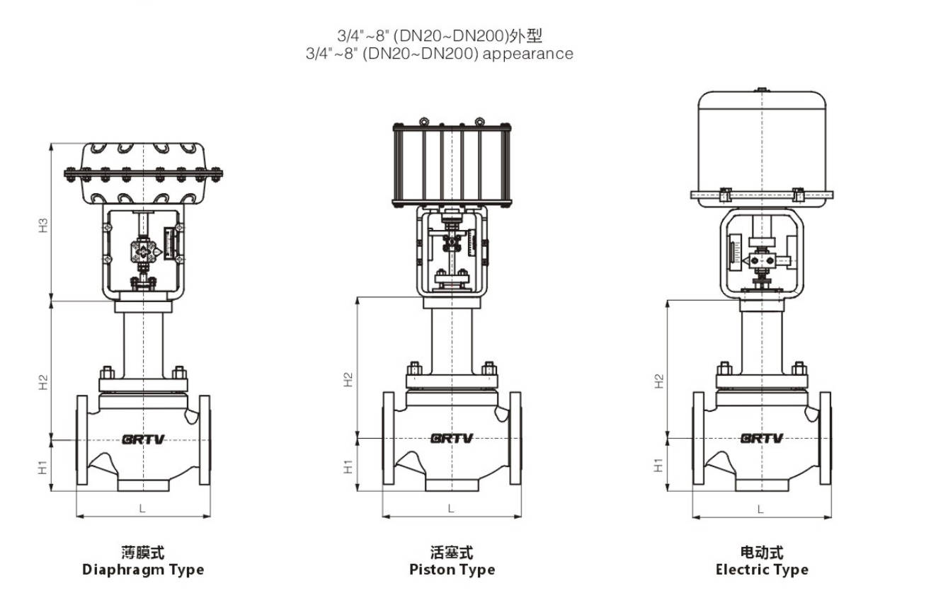
Appearance Dimension
| Nominal Diameter (inch) | Nominal Diameter (mm) | L ANSI150 PN16/25 (GB/T12221) | L ANSI150 PN16/25 (GB/T17213.3) | L ANSI300 PN40 (GB/T17213.3) | L ANSI600 PN64/100 (GB/T17213.3) | H1 | H2 | H3 | Electrical Actuator | Pneumatic Actuator |
|---|
| 3/4 | 20 | 150 | 184 | 194 | 206 | 40 | 135 | 274 | 381LSA-20 | ZJHA/B-22 |
| 1 | 25 | 160 | 184 | 197 | 210 | 43 | 146 | 274 | 381LSA-20 | ZJHA/B-22 |
| 1 1/4 | 32 | 180 | 210 | 235 | 251 | 45 | 163 | 302 | 381LSB-30 | ZJHA/B-23 |
| 1 1/2 | 40 | 200 | 222 | 235 | 251 | 56 | 163 | 302 | 381LSB-30 | ZJHA/B-23 |
| 2 | 50 | 230 | 254 | 267 | 286 | 73 | 165 | 302 | 381LSB-30 | ZJHA/B-23 |
| 2 1/2 | 65 | 290 | 276 | 292 | 311 | 83 | 217 | 375 | 381LSB-50 | ZJHA/B-34 |
| 3 | 80 | 310 | 298 | 317 | 337 | 102 | 235 | 375 | 381LSB-50 | ZJHA/B-34 |
| 4 | 100 | 350 | 352 | 368 | 394 | 110 | 236 | 375 | 381LSB-50 | ZJHA/B-34 |
| 5 | 125 | 400 | 420 | 425 | 457 | 146 | 340 | 465 | 381LSC-99 | ZJHA/B-45 |
| 6 | 150 | 480 | 451 | 473 | 508 | 170 | 340 | 465 | 381LSC-99 | ZJHA/B-45 |
| 8 | 200 | 600 | 543 | 568 | 610 | 220 | 383 | 465 | 381LSC-99 | ZJHA/B-45 |
Manufacturing Process
Step 1: Order and Design
Based on the operating conditions parameters provided by the customer, such as pressure, temperature, flow rate, medium type and leakage level requirements, the structural form, valve body material, valve core/valve cage fitting dimensions and bellows sealing scheme of the bellows cage type control valve are determined. Subsequently, the drawing design, material list and process review are completed to prepare for the subsequent production.
Step 2: Forging & Casting
According to the design requirements, the main pressure-bearing components such as the valve body and valve cover are forged or precisely cast. For bellows cage type control valves, the materials of the valve body and valve cover usually need to meet the requirements of pressure resistance, corrosion resistance and temperature resistance. After the blank is completed, heat treatment, surface cleaning and initial size inspection are carried out to ensure there are no defects such as shrinkage cavities and cracks.
Step 3: Machining
Carry out precise mechanical processing on the valve body, valve seat, valve cage, valve stem, valve cover and connecting components. The key processing points of the bellows cage type control valve include the flow channel size of the valve cage, the mating accuracy of the valve core, the surface finish of the sealing surface, as well as the coaxiality and welding assembly dimensions at the connection part of the bellows, in order to ensure stable regulating performance and sealing performance.
Step 4: Assembly
After the processed components are cleaned, they proceed to the assembly process. The assembly process includes valve seat installation, valve cage positioning, valve core and valve stem connection, bellows component installation, packing assembly, and actuator connection. For bellows cage type control valves, the assembly and protection of the bellows component are particularly crucial. It is necessary to avoid deformation due to force to ensure that it can achieve reliable dynamic sealing.
Step 5: Testing & Quality Assurance
After assembly is completed, a comprehensive inspection of the bellows cage type control valve is carried out, including size recheck, shell strength test, sealing test, air tightness test, stroke calibration and operation test. If there are any special requirements, wave tube leakage detection and performance testing can also be conducted to ensure that the valve meets the relevant standards and customer usage requirements.
Step 6: Painting and Finishing
After passing the inspection, the outer surface of the valve is treated with rust removal, primer application and topcoat spraying. The nameplate, labels, protective covers and packaging are also completed. Before leaving the factory, the finished product needs to be rechecked for complete appearance, accessories and documents to ensure it is not damaged during transportation and meets the installation requirements at the site.
If you need, I can also continue to help you format it into an English version that is more like a product catalogue / official website style, or change it into a version that is more like a factory production process manual.
Applications
Suitable for regulating highly toxic, flammable, explosive, volatile and rare precious metal media. This valve can also be used in vacuum conditions. The leakage of the regulating valve complies with the ANSI B16.104 standard. The regulating valve is widely used in multi-spring diaphragm actuators, with a compact structure and high output force.
These valves are widely used in:
Agriculture and Irrigation
Factory Environment
Why Choose Us
Superior Quality

Our valves are manufactured using premium materials and undergo rigorous quality testing to ensure reliable performance in demanding industrial applications.
Advanced Technology

Equipped with state-of-the-art CNC machining centers and precision manufacturing equipment, we deliver valves with exceptional accuracy and consistency.
Competitive Pricing

Through optimized manufacturing processes and bulk material procurement, we offer high-quality valves at competitive prices without compromising on quality.
Expert Support

Our experienced technical team provides comprehensive support from product selection to after-sales service, ensuring optimal valve performance for your specific application.