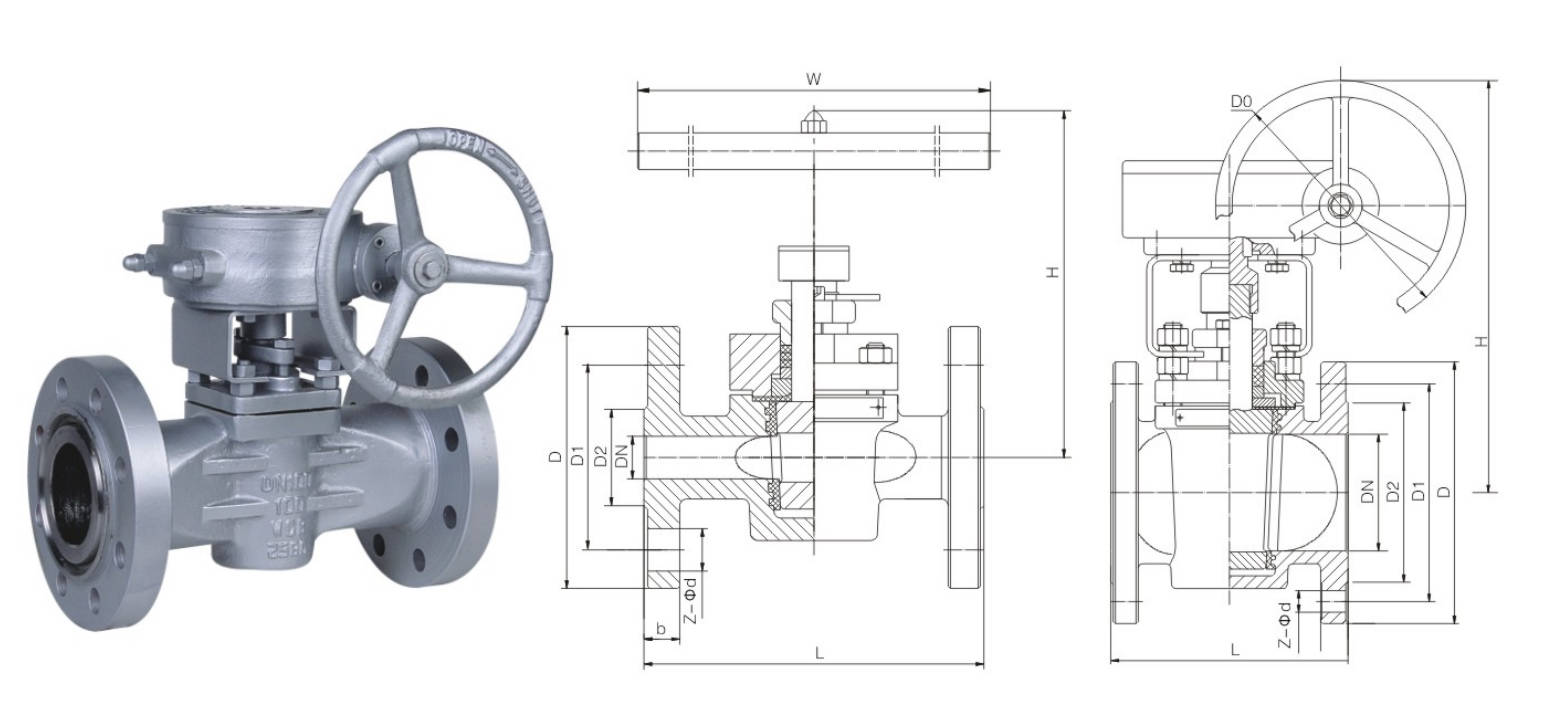
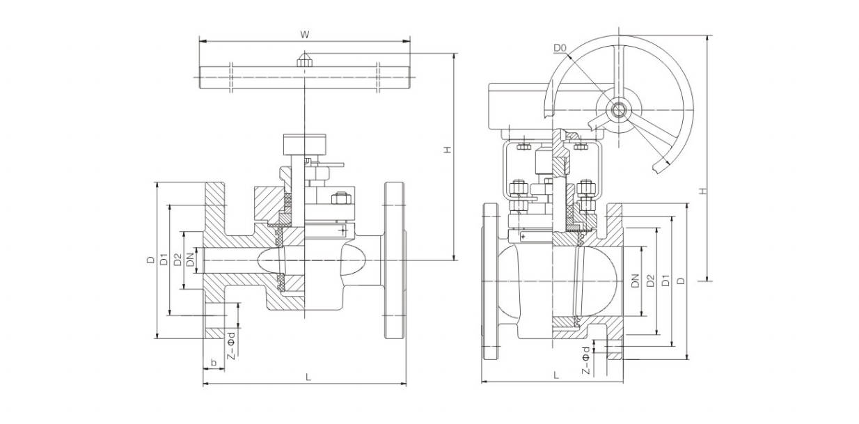
Main external and connection Dimension
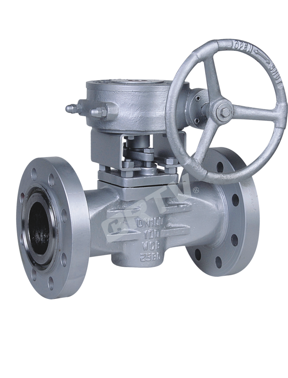
DIN X43F Series – PN1.6 / 2.5 MPa
| NPS (in) | DN (mm) | L | D | D1 | D2 | b | Z-d | H | W | Do | WT (kg) |
|---|
| 1/2 | 15 | 130 | 95 | 65 | 45 | 16 | 4-Φ14 | 150 | 300 | — | 6.5 |
| 3/4 | 20 | 150 | 105 | 75 | 58 | 18 | 4-Φ14 | 155 | 300 | — | 7.0 |
| 1 | 25 | 160 | 115 | 85 | 68 | 18 | 4-Φ14 | 160 | 300 | — | 8.0 |
| 1-1/4 | 32 | 180 | 140 | 100 | 78 | 18 | 4-Φ18 | 180 | 350 | — | 11 |
| 1-1/2 | 40 | 200 | 150 | 110 | 88 | 18 | 4-Φ18 | 190 | 400 | — | 15 |
| 2 | 50 | 230 | 165 | 125 | 102 | 20 | 4-Φ18 | 200 | 500 | — | 18 |
| 2-1/2 | 65 | 290 | 185 | 145 | 122 | 18 | 4-Φ18 | 220 | 500 | — | 26 |
| 3 | 80 | 310 | 200 | 160 | 138 | 20 | 8-Φ18 | 230 | 550 | — | 36 |
| 4 | 100 | 350 | 220 | 180 | 158 | 20 | 8-Φ18 | 380 | — | 300 | 44 |
| 6 | 150 | 480 | 285 | 240 | 212 | 22 | 8-Φ22 | 520 | — | 320 | 60 |
| 8 | 200 | 600 | 340 | 295 | 268 | 24 | 12-Φ22 | 580 | — | 320 | 81 |
| 10 | 250 | 730 | 405 | 355 | 320 | 26 | 12-Φ26 | 620 | — | 350 | 147 |
| 12 | 300 | 850 | 460 | 410 | 378 | 28 | 12-Φ26 | 680 | — | 380 | 217 |
DIN X43F Series – PN25
| NPS (in) | DN (mm) | L | D | D1 | D2 | b | Z-d | H | W | Do | WT (kg) |
|---|
| 1/2 | 15 | 130 | 95 | 65 | 45 | 16 | 4-Φ14 | 150 | 300 | — | 6.5 |
| 3/4 | 20 | 150 | 105 | 75 | 58 | 18 | 4-Φ14 | 155 | 300 | — | 7.0 |
| 1 | 25 | 160 | 115 | 85 | 68 | 18 | 4-Φ14 | 160 | 300 | — | 8.0 |
| 1-1/4 | 32 | 180 | 140 | 100 | 78 | 18 | 4-Φ18 | 180 | 350 | — | 11 |
| 1-1/2 | 40 | 200 | 150 | 110 | 88 | 18 | 4-Φ18 | 190 | 400 | — | 15 |
| 2 | 50 | 230 | 165 | 125 | 102 | 20 | 8-Φ18 | 200 | 500 | — | 18 |
| 2-1/2 | 65 | 290 | 185 | 145 | 122 | 22 | 8-Φ18 | 220 | 500 | — | 26 |
| 3 | 80 | 310 | 200 | 160 | 138 | 24 | 8-Φ18 | 230 | 550 | — | 36 |
| 4 | 100 | 350 | 235 | 190 | 162 | 24 | 8-Φ22 | 380 | — | 300 | 44 |
| 6 | 150 | 480 | 300 | 250 | 218 | 28 | 8-Φ26 | 520 | — | 320 | 60 |
| 8 | 200 | 600 | 360 | 310 | 278 | 30 | 12-Φ26 | 580 | — | 320 | 81 |
| 10 | 250 | 730 | 425 | 370 | 335 | 32 | 12-Φ30 | 620 | — | 350 | 147 |
| 12 | 300 | 850 | 485 | 430 | 395 | 34 | 16-Φ30 | 680 | — | 380 | 217 |
DIN X43F Series – PN4.0 / 6.4 MPa
| NPS (in) | DN (mm) | L | D | D1 | D2 | b | Z-d | H | W | Do | WT (kg) |
|---|
| 1/2 | 15 | 130 | 95 | 65 | 45 | 16 | 4-Φ14 | 150 | 300 | — | 7 |
| 3/4 | 20 | 150 | 105 | 75 | 58 | 18 | 4-Φ14 | 155 | 300 | — | 7.5 |
| 1 | 25 | 160 | 115 | 85 | 68 | 18 | 4-Φ14 | 160 | 300 | — | 8.5 |
| 1-1/4 | 32 | 180 | 140 | 100 | 78 | 18 | 4-Φ18 | 180 | 350 | — | 13 |
| 1-1/2 | 40 | 200 | 150 | 110 | 88 | 18 | 4-Φ18 | 190 | 400 | — | 17 |
| 2 | 50 | 230 | 165 | 125 | 102 | 20 | 4-Φ18 | 200 | 500 | — | 22 |
| 2-1/2 | 65 | 290 | 185 | 145 | 122 | 22 | 8-Φ18 | 220 | 500 | — | 29 |
| 3 | 80 | 310 | 200 | 160 | 138 | 24 | 8-Φ18 | 230 | 550 | — | 41 |
| 4 | 100 | 350 | 235 | 190 | 162 | 24 | 8-Φ22 | 380 | — | 300 | 50 |
| 6 | 150 | 480 | 300 | 250 | 218 | 28 | 8-Φ26 | 520 | — | 320 | 68 |
| 8 | 200 | 600 | 375 | 320 | 285 | 34 | 12-Φ30 | 580 | — | 320 | 87 |
| 10 | 250 | 730 | 450 | 385 | 345 | 38 | 12-Φ33 | 620 | — | 350 | 155 |
| 12 | 300 | 850 | 515 | 450 | 410 | 42 | 16-Φ33 | 680 | — | 380 | 230 |
DIN X43F Series – PN6.4 MPa
| NPS (in) | DN (mm) | L | D | D1 | D2 | b | Z-d | H | W | Do | WT (kg) |
|---|
| 1/2 | 15 | 130 | 105 | 75 | 45 | 20 | 4-Φ14 | 150 | 300 | — | 9 |
| 3/4 | 20 | 150 | 105 | 75 | 58 | 20 | 4-Φ14 | 160 | 300 | — | 12 |
| 1 | 25 | 160 | 140 | 100 | 68 | 24 | 4-Φ18 | 160 | 300 | — | 14 |
| 1-1/4 | 32 | 180 | 155 | 110 | 75 | 24 | 4-Φ22 | 180 | 350 | — | 18 |
| 1-1/2 | 40 | 200 | 170 | 125 | 88 | 28 | 4-Φ22 | 190 | 400 | — | 21 |
| 2 | 50 | 230 | 180 | 135 | 102 | 26 | 4-Φ22 | 200 | 500 | — | 27 |
| 2-1/2 | 65 | 290 | 205 | 160 | 122 | 26 | 8-Φ22 | 220 | 500 | — | 34 |
| 3 | 80 | 310 | 215 | 170 | 138 | 28 | 8-Φ22 | 230 | 550 | — | 46 |
| 4 | 100 | 350 | 250 | 200 | 162 | 30 | 8-Φ26 | 380 | — | 300 | 58 |
| 6 | 150 | 480 | 345 | 280 | 218 | 36 | 8-Φ33 | 520 | — | 320 | 78 |
| 8 | 200 | 600 | 415 | 345 | 285 | 42 | 12-Φ36 | 580 | — | 320 | 105 |
Manufacturing Process
Step 1: Order and Design
Based on the pressure rating, nominal diameter, material, connection type, and operating conditions provided by the customer, the structural design and dimensional requirements for the sleeve-type plug valve are confirmed. Drawing designs, bills of materials, and manufacturing processes are finalized to prepare for subsequent production.
Step 2: Forging & Casting
Major pressure-bearing components, such as the valve body and bonnet, are typically formed through forging or casting to ensure the blanks possess sufficient strength and density. For sleeve-type plug valves, the blanks undergo visual inspection after forming and are heat-treated as required to enhance material properties.
Step 3: Machining
Precision machining is performed on the valve body interior, flange faces, sealing contact surfaces, valve stem bores, and plug components to ensure dimensional accuracy and surface finish. The key focus of machining for sleeve-type plug valves is the fit accuracy between the valve body interior and the plug and sleeve, ensuring that sealing performance and operating torque meet specifications.
Step 4: Assembly
The sleeve, plug, valve stem, seals, gaskets, and operating mechanism are assembled in sequence, and the installation positions and preload of each component are adjusted. During the assembly of the sleeve-type plug valve, special attention must be paid to the integrity of the sleeve installation to avoid scratches, misalignment, or improper press-fitting that could compromise sealing performance.
Step 5: Testing & Quality Assurance
After assembly, the sleeve-type plug valve undergoes shell strength testing, sealing tests, and opening/closing operation tests to ensure the valve is leak-free and operates smoothly under specified pressure. Concurrently, dimensional inspections, material verification, and visual inspections are conducted to ensure the product meets relevant standards and customer requirements.
Step 6: Painting and Finishing
After passing the tests, the valve undergoes surface cleaning, rust prevention treatment, and spray painting for identification. Finally, the nameplate is installed, the flanges are protected, and the valve is packaged and stored to ensure the product remains in good condition during transportation and delivery.
Applications
Primarily used in piping systems for the petroleum, chemical, pharmaceutical, fertilizer, and power industries
These valves are widely used in:
Agriculture and Irrigation
Factory Environment
Why Choose Us
Superior Quality

Our valves are manufactured using premium materials and undergo rigorous quality testing to ensure reliable performance in demanding industrial applications.
Advanced Technology

Equipped with state-of-the-art CNC machining centers and precision manufacturing equipment, we deliver valves with exceptional accuracy and consistency.
Competitive Pricing

Through optimized manufacturing processes and bulk material procurement, we offer high-quality valves at competitive prices without compromising on quality.
Expert Support

Our experienced technical team provides comprehensive support from product selection to after-sales service, ensuring optimal valve performance for your specific application.